Intel
®
EP80579 Integrated Processor Product Line May 2010
Order Number: 320068-005US 300
Schematics Checklist—Intel
®
EP80579 Integrated Processor Product Line
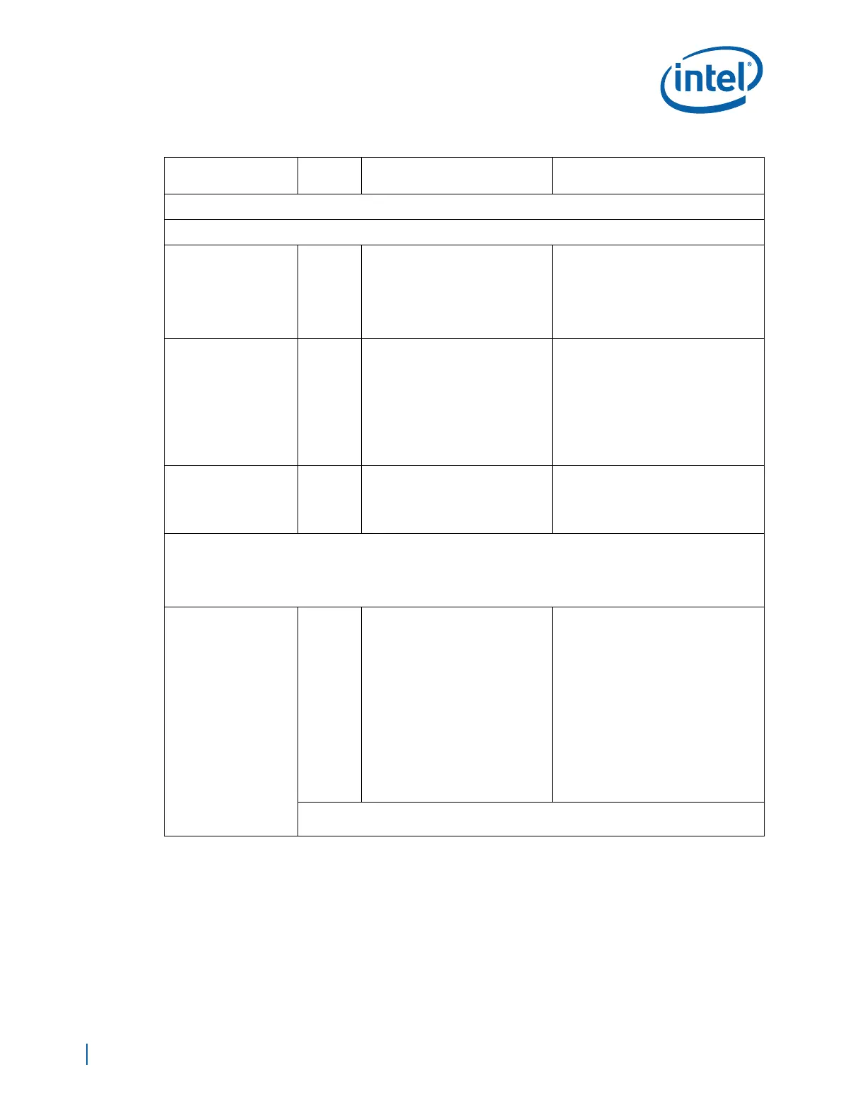
Acceleration and I/O Complex (AIOC)
Controller Area Network (CAN) Interface
CN0TXD,
CN1TXD
O
• Connect directly to the Driver
(D) inputs of CAN Transceivers
•One CAN Transceiver per
channel
• Connect CAN Low/High (CANL/
CANH) outputs to CAN Connector
Note:
• Can be left as NC when the port is
not connected to an interfacing
device.
CN0TXEN,
CN1TXEN
O
• Connect to Standby/Slope
Control (Rs) inputs of CAN
Transceivers
• Driver is switched off and the
receiver is activated if a high logic is
applied to Rs and remains in sleep
mode until the circuit is activated by
a low logic level on Rs
Note:
• Can be left as NC when the port is
not connected to an interfacing
device.
CN0RXD,
CN1RXD
I
• Connect directly to the Receive
(R) outputs of CAN Transceivers
Note:
• Must be pulled high through a 10
KΩ resistor when the interface is not
used or connected to an interfacing
device
Gigabit Ethernet (GbE) Interface
Note:
• GBE Port 0 supports Wake-On-LAN (WOL); hence GBE Port 0 Block resides in the Sustain Power Well within
EP80579. It is required that all GBE Port 0 (Transmit/Receive) interface signals on the platform be powered by GBE
Standby Voltage. GBE Port 1&2 should be powered by GBE core power.
GBEn_TxDATA[3:0]
O
RGMII Mode
• Interconnect each Port Transmit
Data (GBEn_TxDATA[3:0]) to
the corresponding Port Transmit
Data of the RGMII PHY Device
• Pull up GBE Port 0 Transmit
Data signals to EP80579 2.5V
Standby Voltage (VCCSUS25)
using a 1.2KΩ ± 5% resistors.
• Pull up GBE Port 1&2 Transmit
Data signals to GBE 2.5V
using a
1.2KΩ ± 5% resistors.
• Leave signals for any unused
Port as no connect.
RMII Mode
• Interconnect the lower two bits of
each Port Transmit Data
(GBEn_TxDATA[1:0]) to the
corresponding Port Transmit Data of
the RMII PHY Device.
• Pull up GBE Port 0 Transmit Data
signals to EP80579 3.3V Standby
Voltage (VCCGBEPSUS)
using a
1.2KΩ ± 5% resistors.
• Pull up GBE Port 1&2 Transmit Data
signals to GBE 3.3V
using a 1.2KΩ ±
5%
resistors
• Leave all unused Transmit Data
signals as no connect.
Note:
• Can be left as NC when the port is not used in either mode.
Table 100. Schematic Checklist (Sheet 17 of 26)
Checklist Items
I/O Type
(Default)
Recommendations Comments
 Loading...


