Intel
®
EP80579 Integrated Processor Product Line May 2010
Order Number: 320068-005US 302
Schematics Checklist—Intel
®
EP80579 Integrated Processor Product Line
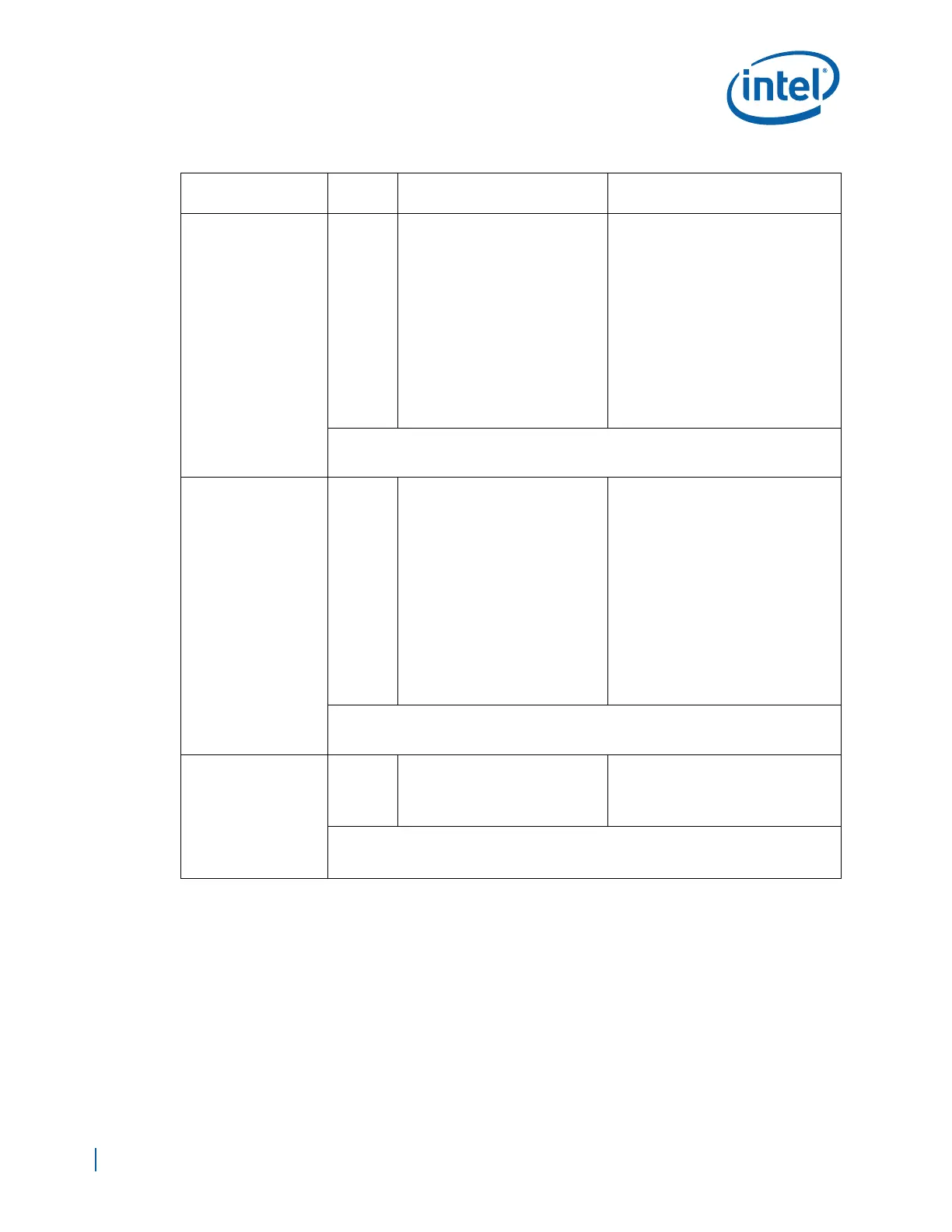
GBEn_RxCLK
I
RGMII Mode
• Interconnect each Port Receive
Clock (GBEn_RxCLK) to the
corresponding Port Receive
Clock of the RGMII PHY Device
• Pull up GBE Port 0 Receive
Clock signal to EP80579 2.5V
Standby Voltage (VCCSUS25)
using a 1.2KΩ ± 5% resistor.
• Pull up GBE Port 1&2 Receive
Clock signals to GBE 2.5V
using
a
1.2KΩ ± 5% resistors.
• Pull-down all unused Receive
Clock signals to GND
using 10
KΩ
resistors.
RMII Mode
• No used in this mode
• Pull-down all Receive Clock signals
to GND
using 10 KΩ resistors
Note:
• Pull-down all Receive Clock signals to GND
using 10 KΩ resistors when the port is not
used in either mode
GBEn_RxCTL
I
RGMII Mode
• Interconnect each Port Receive
Control (GBEn_RxCTL) to the
corresponding Port Receive
Data Valid (RX_DV) of the
RGMII PHY Device
• Pull up GBE Port 0 Receive
Control signal to EP80579 2.5V
Standby Voltage (VCCSUS25)
using a 1.2KΩ ± 5% resistor.
• Pull up GBE Port 1&2 Receive
Control signals to GBE 2.5V
using a 1.2KΩ ± 5% resistors.
• Pull-down all unused Receive
Control signals to GND
using 10
KΩ
resistors.
RMII Mode
• Interconnect each Port Receive
Control (GBEn_RxCTL) to the
corresponding Port Receive Data
Valid (CRS_DV) of the RMII PHY
Device
• Pull up GBE Port 0 Receive Control
signal to EP80579 3.3V Standby
Voltage (VCCGBEPSUS)
using a
1.2KΩ ± 5% resistor.
• Pull up GBE Port 1&2 Receive
Control signals to GBE 3.3V
using a
1.2KΩ ± 5% resistors
• Pull-down all unused Receive
Control signals to GND
using 10 KΩ
resistors.t
Note:
• Pull-down all Receive Control signals to GND
using 10 KΩ resistors when the port is not
used in either mode
GBE_REFCLK
I
RGMII Mode
• 125 MHz Reference clock
• Sourced from an external clock
or from the RGMII PHY Device.
RMII Mode
• 50 MHz Reference clock.
• External clock to both the MAC and
RMII PHY Device
Note:
• Connect to 125 MHz clock source when the ports are not used in either mode.
•See Section 2.3
Table 100. Schematic Checklist (Sheet 19 of 26)
Checklist Items
I/O Type
(Default)
Recommendations Comments
 Loading...


