EXi: MOD-7 Waveshaping VPM Synthesizer
312
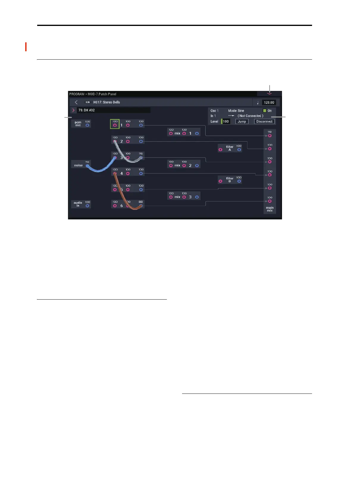
PROGRAM > MOD-7: Patch Panel
4–1: Patch Panel
The patch panel shows an overview of most components in
the MOD-7, and lets you:
• Control the connections between components
(oscillators, filters, mixers, and so on) by selecting
algorithms and/or using patch cables
• Edit input and output levels for all components
• Jump directly to the detailed editing pages for all
components
Using the Patch Panel
Algorithms
Depending on the selected algorithm, many of the MOD-7
elements (VPM oscillators, PCM oscillator, Noise
Generator, filters, mixers, etc.) are connected by default,
even without using any patch cables. The lines and arrows
on the Patch Panel show these “normal” signal paths.
You can change any and all of these default connections
using patch cables, as desired. Plugging a cable into an input
jack disconnects the “normal” path, and uses the signal from
the cable instead. Plugging a cable into an output jack does
not affect the normal path, since a single output can be
connected to any number of inputs.
For more information on using algorithms, see “4–1a:
Algorithm Select” on page 313.
Basic patching rules
Inputs are colored red, and outputs are colored blue.
Each input can be connected to a single output, and no more
(although a single output can be connected to multiple
inputs, as described below). If you want to route two outputs
to a single input, use one of the mixers to merge the outputs
first.
Plugging a cable into an output jack lets you use the signal
elsewhere on the patch panel, and does not interrupt the
“normal” path. You can also connect a single output to any
number of inputs, if you like; this is sometimes called a
“mult.” The signal strength remains the same, as if you were
using a distribution amplifier.
Connections from one input to another, or from one output to
another, are not allowed.
Creating and deleting connections
You can make connections on the Patch Panel by touch-
dragging from an output to an input, or vice-versa.
Similarly, you can delete connections by touching an input
jack and dragging the cable away. To delete all connections
from an output in a single step, touch the output jack and
then press the Disconnect button in the Parameter Details
area.
To completely clear the Patch Panel, so that you can start
from scratch, open the menu and select the Delete All
Connections command.
For more details on using NAUTILUS Patch Panels, see
“Using the Patch Panel” on page 267.
Setting input and output levels
You can edit the main input and output levels for each block
directly from the Patch Panel. To do this:
1. Select the jack whose input level you want to edit.
For instance, select Input 2 of VPM Oscillator 4.
2. Use the standard data-entry controls to set the level as
desired.
Note that modulation can affect these levels, as well–so you
may have to look at the individual edit pages to get the
complete picture.

 Loading...