Wake on LAN Mode/Low-PowerBCM5718 Programmer’s Guide
Broadcom®
January 29, 2016 • 5718-PG108-R Page 217
Pattern Data Structure
The maximum number of entries in either 10/100 or 1000 mode is 128. The Ethernet controller cannot process
a pattern that requires more than 128 entries. The size of an entry will vary based on 10/100 or 1000 Mbps
mode. Additionally, all unused rows must be initialized with zeros. The WOL hardware cannot process an entry
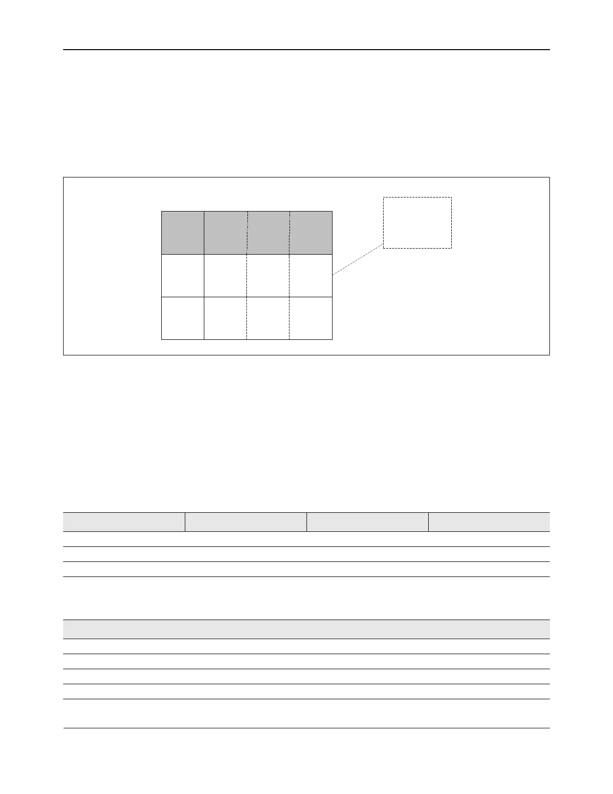
unless unused rows and rules have been zeroed out (see Figure 48).
Figure 48: Unused Rows and Rules Must Be Initialized with Zeros
Frame patterns are stored as data structures in memory. A control word is always present in a 64 bit entry/row.
The control word describes proceeding data fields in the entry.
In 10/100 Mbps mode, one WOL entry requires three 64-bit wide rows (see Table 76). The total length of an
entry is 192 bits. Each 64-bit row contains a 16-bit control word, which identifies byte enables (see Ta bl e 76 ).
The remaining 48-bits contains 2-byte rules. The 2-byte rules are distributed across three streams: S, S+1, and
S+2. The next row’s 2-byte rules will correspond to three more streams: S+3, S+4, and S+5. Both Table 75 and
Ta b le 7 6 use Sx notation to denote separate comparison streams. The D0 notation indicates the first 2 bytes in
the packet stream are compared.
Table 75: 10/100 Mbps Mode Frame Patterns Memory
63 48 47 32 31 16 15 0
CTRL012 S0D0 S1D0 S2D0
CTRL345 S3D0 S4D0 S5D0
CTRL678 S6D0 S7D0 S8D0
Table 76: Frame Control Field for 10/100 Mbps Mode
Bits Field Description Access
63:62 Reserved
61 S0 High Byte Enable Enable S0 higher byte for comparison RW
60 S0 Low Byte Enable Enable S0 lower byte for comparison RW
59 S1 High Byte Enable Enable S1 higher byte for comparison RW
USED
00,00 00,00 00,00
00,00 00,00 00,00
Control Stream 1 Stream 2 Stream 3
00,00
00,00
Unused rules are
initialized with 0
 Loading...