4 Message Display
9-66 SmartAXIS Touch User’s Manual
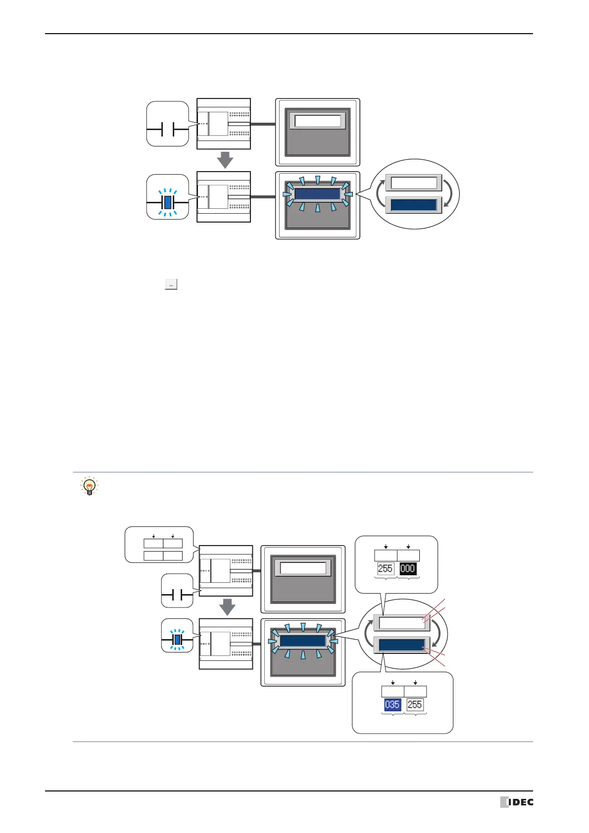
■ Blink
Flashes the message or plate color.
Enable: Turn this check box on to make messages flash.
Trigger device: Specifies the bit device that wlll be used as a condition to trigger flashing.
Click to display the Device Address Settings dialog box. For the device address configuration
procedure, refer to Chapter 2 “5.1 Device Address Settings” on page 2-62.
When the value of device is 0, the color specified in Text Color on the Format tab or in Plate
Color on the View tab will be displayed.
When the value of device is 1, the color displayed when the device is 0 and the color specified in
Text Color or Plate Color will be displayed alternately.
Flash intervals are set in Blinking Cycle on the System tab in the Project Settings dialog box.
Text Color: This selects the color (color: 256 colors, monochrome: 8 shades) of text when flashing.
Click this button to display the Color Palette. Select a color from the Color Palette.
This can be set only when the Enable check box is cleared.
Plate Color: This selects the plate color (color: 256 colors, monochrome: 8 shades) when flashing.
Click this button to display the Color Palette. Select a color from the Color Palette.
This can be set only when the Enable check box is cleared.
TouchExternal device
0
1
FT SERIES
FT SERIES
FT SERIES
FT SERIES
Flashing
Trigger device
Text Color and Plate Color are specified in Device under Change Color by Device when the Enable
check box has been selected in both Blink and Change Color by Device.
Example: When the Device is D0
FT SERIES
FT SERIES
Flashing
TouchExternal device
FT SERIES
FT SERIES
D0
0x00
0xF7
Lower byteUpper byte
D1
0xF7
0x23
Lower byteUpper byte
Text Color
Plate Color
Text color when blinking
Plate color when blinking
Text ColorPlate Color
Text color
when blinking
Plate color
when blinking
0
1
D0=
Lower byteUpper byte
0x000xF7
D1=
0xF70x23
Device
Trigger device