EXi: MS-20EX
272
3. Adjust the EG 1 Delay and Attack controls to create
the desired delay and fade-in times
CONTROL INPUT jack
This controls the level of the MVCA. It’s normalled to the
EG 1 output, but you can patch in any other control signal.
This input includes built-in lowpass filtering, which acts as a
smoother on the control signal.
IN jack
This is the input to the VCA. Unlike the CONTROL INPUT,
this does not have any lowpass filtering.
OUT jack
This is the output of the VCA–the input signal scaled by the
control signal.
6–1g: NOISE GENERATOR
These outputs provide pink and white noise, respectively.
You can use these as sound sources or as modulation signals.
PINK output jack
Pink noise has a darker sound than white noise, with reduced
high frequency components.
WHITE output jack
White noise is classic broad-band noise.
Note that white noise is also available as a waveform in
VCO 1.
6–1h: Mod Wheel and Mod Switch
The Mod Wheel and Switch jacks allow you to select any
AMS source (controllers, EGs, LFOs, step sequencer etc.),
scale it via Intensity, and then route the signal into the patch
panel.
For more information, see “Mod Wheel and Mod Switch” on
page 275.
(Mod Wheel) jack
This lets you select, scale, and route the first AMS signal.
This could be the Mod Wheel, if you wish–but it could also
be any other AMS source.
(Mod Switch) jack
This lets you select, scale, and route the second AMS signal.
You can use any AMS source, including continuous sources
such as LFOs and EGs; the selection is not limited to on/off
switches.
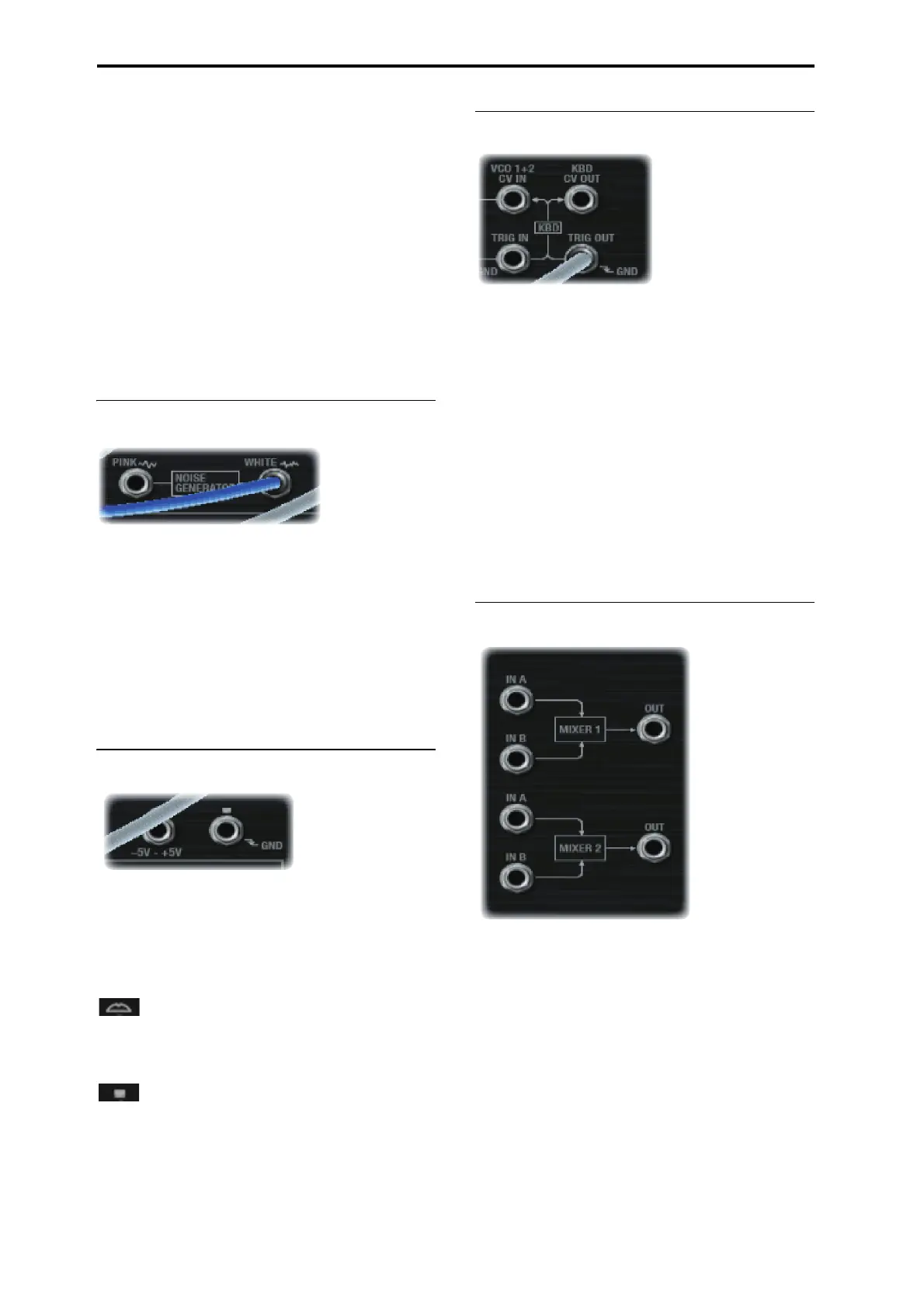
6–1i: Keyboard Trigger and CV outputs
KBD CV OUT jack
This allows you to route the keyboard’s control voltage
(which is a signal representing the current note) to other
parts of the synthesizer.
KBD TRIG OUT jack
Whenever you play a key on the keyboard, a trigger signal is
generated.
Using the Parameter Details box, you can select whether this
trigger represents Note Gate + Sustain, or Note Gate only.
Note Gate + Sustain is the default, and is most appropriate
for general use.
Note Gate is useful for keyboard trigger operation within
self-triggering patches. For more information, see “Tip:
Creating self-triggering patches” on page 269.
6–1j: MIXERS 1 and 2
MIXER 1
This is a simple 2-in, 1-out mixer; you can use it for merging
and scaling either control or audio signals. Note that you can
also use this to invert the polarity of a signal.
The levels of inputs A and B are controlled by knobs on the
MG, EGs, and Modulation page, and can be modulated via
AMS; for more information, see “5–1g: Mixers” on
page 266.
IN A jack
This is the first input to the mixer.
IN B jack
This is the second input to the mixer.
OUT jack
This is the merged output of IN A and IN B.

 Loading...