SAMPLING > Recording 0–1: Recording
577
Press the SAMPLING REC button to enter sampling
standby mode, where you can adjust the signal level with the
slider. Start by setting the level to “0.0”, and bring up the
level shown by the bar so that it does not exceed 0 dB.
Note that if the “Recording Level” is still distorted even
after you lower the signal, the signal might still be
distorted (if you are using analog inputs) depending on
the settings of the AUDIO INPUT stage or the internal
effects.
See the Recording– Audio Input page to check whether
the signal levels of the AUDIO INPUT stage are
overloading. Distortion is occurring due to signal
overload in the AUDIO INPUT stage if “ADC
OVERLOAD!” appears above the “Recording Level”
bar. Adjust the levels in “Analog Input Setup” so that the
message does not appear.
If the signal distorts even after you turn down the analog
input gain, the settings of the internal effects may be
causing the distortion. Try turning (Input 1, 2) “Level”
(0–8a) down, or adjust the effect settings.
CLIP !
If 0 dB is exceed, the display will indicate “CLIP !” This
means that the level of the sampling signal is too high, so
adjust the level as described under “Setting levels” on
page 27.
Note: When signals are input to the AUDIO INPUT 1/2
jacks, adjust the level in “Analog Input Setup” so that they
are at their maximum without “ADC OVERLOAD!” being
displayed. This will let you sample at the widest dynamic
range possible. Further, set the “Level” (0–8a) to “127”, and
adjust the “Recording Level” (0–1c, 0–8b) so that the
“CLIP!” message does not display.
Note: If you have sampled at a low input level, you can use
the Normalize/Level Adj. menu command to amplify the
level to the maximum possible without clipping. For more
information, see “Normalize/Level Adjust” on page 617.
0–1d: REC Sample Setup
Save to [RAM, Disk]
Specifies the destination to which the data will be written
during sampling.
RAM: The sound will be sampled into RAM for use in
SAMPLING mode.
You can check the remaining amount of RAM in the section
labeled “0–1f: Free Sample Memory/Locations,” as
described on page 579.
Note: The amount of RAM available for user sampling will
vary depending upon both the amount of physical RAM
installed, and the size of the currently loaded EXs banks. For
more information, see “Sampling and RAM” on page 571.
Data written into RAM will be lost when the power is
turned off, so you must save it if you want to keep it.
Disk: The sound will be recorded to drive as a WAVE file.
You can select a drive (internal or USB), directory, and name
for the recorded file using the Select Directory/File for
Sample to Disk menu command.
Once recorded, you can audition the sample directly from
the Select Directory/File for Sample to Disk window; just
select the file and press the SAMPLING START/STOP
button. To stop playback, press the SAMPLING
START/STOP button again.
If the sample will fit into RAM, you can also load it into
SAMPLING mode (using the Load command in MEDIA
mode).
You cannot load a drive sample (WAVE file) that exceeds
the amount of available RAM.
Mode [L-Mono, R-Mono, Stereo]
Specifies the channel(s) that you want to sample, and specify
whether a mono or stereo sample will be created. For more
information, see “Source Bus” on page 581.
L-Mono: The L channel of the Source Bus will be sampled
in mono.
R-Mono: The R channel of the Source Bus will be sampled
in mono.
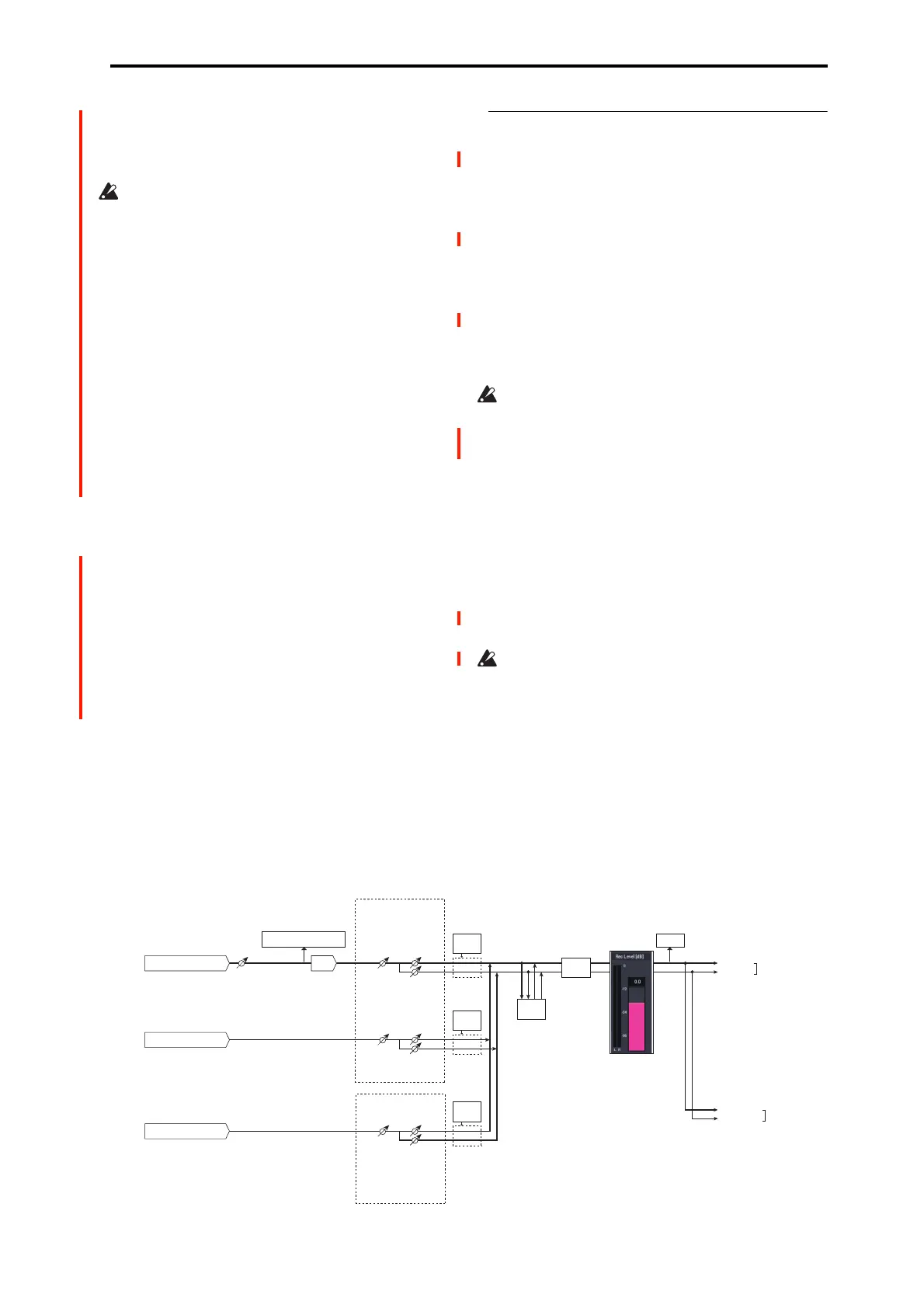
AUDIO INPUT 1, 2
ADC
Analog to
Digital
Converter
LEVEL
(MIC/LINE)
(MIN...MAX)
ADC OVERLOAD !
L-Mono
R-Mono
Stereo
REC Sample Setup
"Mode" (0–1d)
"Level"
[127=0dB]
"Pan"
Insert
Eects
CLIP !!
"Recording Level" (0–1c)
[–inf ... 0.0dB ... +18.0dB]
"Audio Input" (0–8a)
USB A (CD Drive: L, R)
Insert
Eects
L/MONO
"Source Bus" (0-8c)
= L/R
R
AUDIO
OUTPUT
Bus(IFX/Indiv.)
= L/R or IFX1-12
"Level"
[127=0dB]
"Pan"
Total
Eects
Master
Eects
USB B (1, 2)
"Level"
[127=0dB]
"Pan"
Insert
Eects
"CD-R/RW
Audio Input" (5-1b)
Bus(IFX/Indiv.)
= L/R or IFX1-12

 Loading...