PROGRAM > Filter 3–2: Filter1 Mod.
67
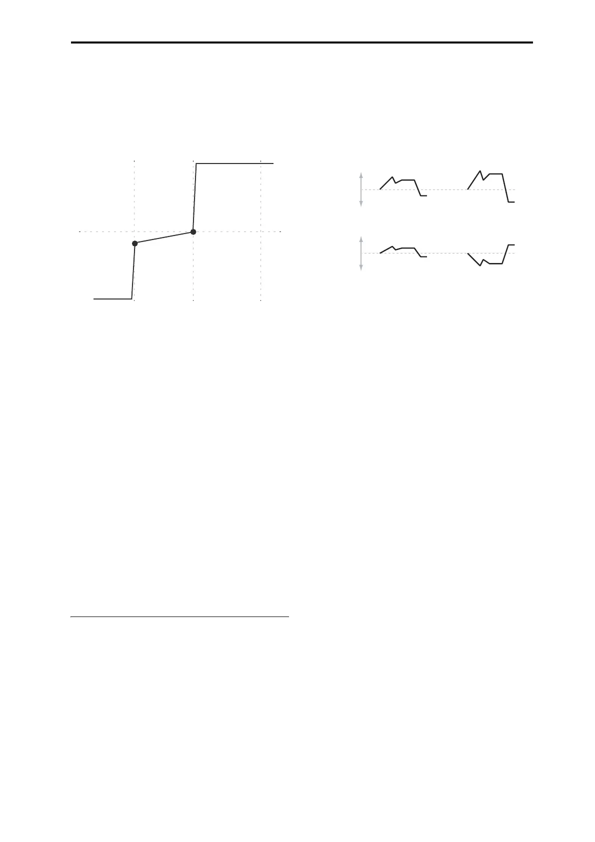
+Inf and –Inf ramps
+Inf and –Inf are special settings which create abrupt
changes for split-like effects. When a ramp is set to +Inf or –
Inf, the keyboard tracking will go to its extreme highest or
lowest value over the span of a single key.
+Inf and –Inf Ramps
Note: If you set the Center-High ramp to +Inf or –Inf, the
High-Top parameter will be grayed out. Similarly, if you set
the Low-Center ramp to +Inf or –Inf, the Bottom-Low ramp
will be grayed out.
Key Follow
To create the classic Key Follow effect, in which the filter
frequency tracks the pitch of the keyboard:
1. Set the Filter Frequency to 30.
2. Set the Keyboard Track Intensity to +99.
3. Set the Bottom-Low and Low-Center ramps to –50.
4. Set the Center-High and High-Top ramps to +50.
5. Set the Center Key to C4.
The settings for the Low Break and High Break keys don’t
matter in this case.
Filter Keyboard Track is also an AMS
source
You can use the keyboard tracking as an AMS source to
modulate other parameters, just like the envelopes and
LFOs. Simply select Filter Keytrack in the AMS list for the
desired parameter.
3–2b: Filter EG
The Filter1 EG modulates the Filter A and B cutoff
frequencies over time. You can control how strongly the EG
will affect the filters in three different ways:
• Set an initial amount of EG modulation, using the
Intensity to A and B parameters.
• Use velocity to scale the amount of the EG applied to the
filter.
• Use any AMS source to scale the amount of the EG
applied to the filter.
You can use all three of these at once, and the results are
added together to produce the total EG effect.
To set up the EG itself, including attack and release times,
levels, and so on, see “3–4: Filter1 EG,” on page 70.
Velocity to A [–99…+99]
This lets you use velocity to scale the amount of the Filter
EG applied to Filter A.
Velocity control of Filter EG
With positive (+) values, playing more strongly will
increase the effect of the Filter EG, as shown in example B
above.
With negative (–) values, playing more strongly will
introduce the opposite effect of the Filter EG–like inverting
the polarity of the envelope. You can use this in several
different ways:
• You can set an initial positive amount with the Intensity
to A/B parameters, and then reduce this amount with
velocity. In this case, the final effect of the EG is simply
diminished, and not actually inverted, as shown in
example C above.
• You can also set the Velocity to A/B amounts so that
they are greater than the initial amounts of Intensity to
A/B. In this case, the EG will have a positive effect at
low velocities, and an inverted effect at high velocities–
as shown in example D.
Velocity to B [–99…+99]
This lets you use velocity to scale the amount of the Filter
EG applied to Filter B. For more information, see “Velocity
to A,” above.
Intensity to A [–99…+99]
This controls the initial effect of the Filter EG on Filter A’s
cutoff frequency, before any velocity or AMS modulation.
The Filter EG’s shape can swing all the way from +99 to –
99. Positive values increase the cutoff frequency, and
negative values decrease the cutoff frequency. For instance,
see the graphic “Velocity to A,” above. The EG shape in
example A rises up at first, and then falls below 0 towards
the end.
When Intensity to A is set to a positive (+) value, EG’s effect
will match its shape. When the EG rises above 0, the cutoff
frequency will increase.
With negative (–) values, the effect will be in the opposite
direction; when the EG rises above 0, the filter cutoff will
decrease.
Intensity to B [–99…+99]
This controls the initial effect of the Filter EG on Filter B’s
cutoff frequency, before any velocity or AMS modulation.
For more information, see “Intensity to A,” above.
Ramp = –Inf
Ramp = +Inf
Ramp = –50
Low Break Center High Break
B. Velocity to A = +50
C. Velocity to A = –25 D. Velocity to A = –99
In all examples below, Intensity to A = +50
Original
Filter Cuto
Original
Filter Cuto
A. Original EG

 Loading...