Concepts and Features
R&S
®
ZNB/ZNBT
113User Manual 1173.9163.02 ─ 55
plane are related as follows (see also: definition of matched-circuit (converted) admit-
tances):
Y / Y
0
= (1 - Γ) / (1 + Γ)
From this equation, it is easy to relate the real and imaginary components of the com-
plex admittance to the real and imaginary parts of Γ:
2
2
22
0
)Im()Re(1
)Im()Re(1
)/Re(
YYG
,
)Im()Re(1
)Im(2
)/Im(
2
2
0
YYB
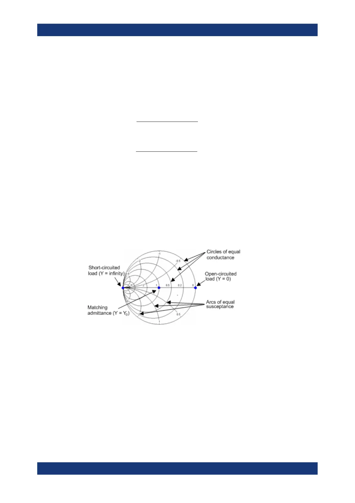
According to the two equations above, the graphical representation in an inverted
Smith chart has the following properties:
●
Real reflection coefficients are mapped to real admittances (conductances).
●
The center of the Γ plane (Γ = 0) is mapped to the reference admittance Y
0
,
whereas the circle with |Γ| = 1 is mapped to the imaginary axis of the Y plane.
●
The circles for the points of equal conductance are centered on the real axis and
intersect at Y = infinity. The arcs for the points of equal susceptance also belong to
circles intersecting at Y = infinity (short circuit point (–1, 0)), centered on a straight
vertical line.
Examples for special points in the inverted Smith chart:
●
The magnitude of the reflection coefficient of a short circuit (Y = infinity, U = 0) is
one, its phase is –180 deg.
●
The magnitude of the reflection coefficient of an open circuit (Y = 0, I = 0) is one, its
phase is zero.
5.2.3.3 Measured Quantities and Trace Formats
The analyzer allows any combination of a display format and a measured quantity. The
following rules can help to avoid inappropriate formats and find the format that is ide-
ally suited to the measurement task.
●
All formats are suitable for the analysis of reflection coefficients S
ii
. The formats
"SWR", "Smith" and "Inv Smith" lose their original meaning (standing wave ratio,
Screen Elements

 Loading...


