Concepts and Features
R&S
®
ZNB/ZNBT
191User Manual 1173.9163.02 ─ 55
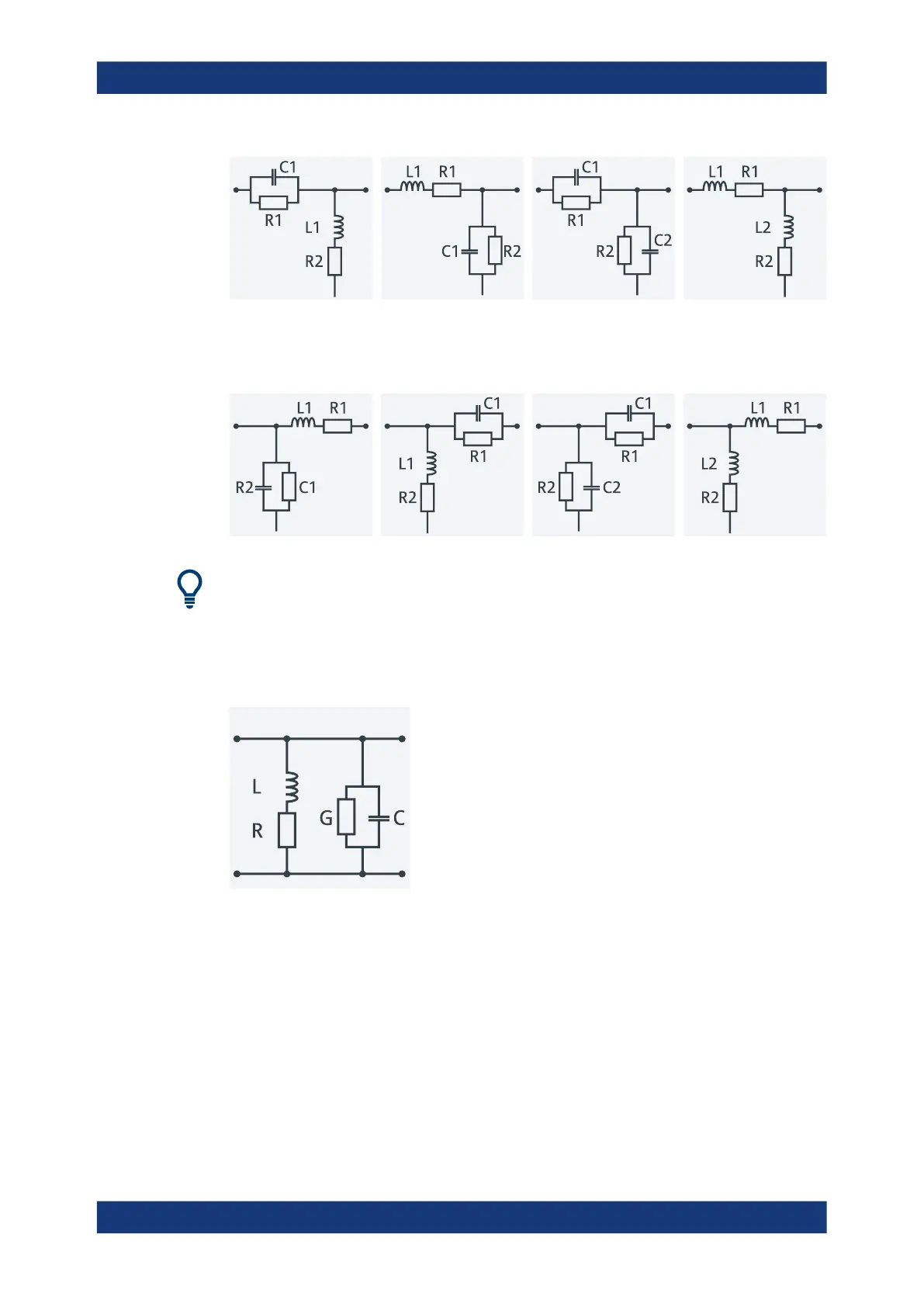
The following networks are composed of a shunt C or L (as seen from the analyzer
port), followed by a serial C or L. They are named Shunt C, Serial L /
Shunt L, Serial C / Shunt C, Serial C / Shunt L, Serial L.
At the GUI, the "capacitance C<i> in parallel with resistance R<i>" circuit blocks can be
replaced by equivalent "capacitance C<i> in parallel with conductance G<i>" circuit
blocks.
In addition, there is also a Shunt L, Shunt C circuit model available, where the
shunt C is defined as a capacitance C in parallel with a conductance G:
5.6.2.4 Circuit Models for 4-Port Networks
The lumped element 4-port transformation networks for (de-)embedding consist of the
following two basic circuit blocks:
●
A capacitor C connected in parallel with a resistor.
●
An inductor L connected in series with a resistor.
The transformation networks comprise various combinations of 3 basic circuit blocks,
where two blocks represent serial elements, the third a shunt element. In the default
setting the resistors are not effective, since the serial Rs are set to 0 Ω, the shunt Rs
are set to 10 MΩ. Moreover, the serial elements can be replaced by imported 2-port S-
Offset Parameters and De-/Embedding

 Loading...


