Concepts and Features
R&S
®
ZNB/ZNBT
196User Manual 1173.9163.02 ─ 55
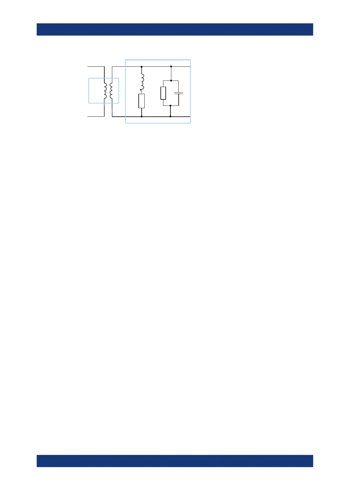
C
G
R
L
Balun
Differential Matching Network
In contrast to standard balanced embedding (4-port), the matching circuit is only
applied to the differential mode port (2-port). It can be specified via a Touchstone s2p
file or by parametrizing a lumped "Shunt L, Shunt C" element model.
5.6.2.9 Fixture Modeling and Deembedding
When performing tasks such as verifying digital high-speed signal structures on printed
circuit boards (PCBs), measurements have to be carried out on certain layers without
the effects of probes, probe pads, vias, lead-ins and lead-outs. This requires the use of
accurate deembedding algorithms to calculate and remove these effects from the mea-
surements, leaving only the result for the area of interest.
Instead of asking the user to define the fixture by parametrizing one of the given lum-
ped circuit models or by "somehow" providing a suitable snp file, the firmware of the
R&S ZNB/ZNBT now also provides integration for third-party tools that model the test
fixture from measured data:
●
AtaiTec's In Situ De-Embedding (ISD), see http://ataitec.com/products/isd/
A pre-installed or service-retrofitted version is available with option R&S ZNB/
ZNBT-K220
●
PacketMicro's Smart Fixture De-embedding (SFD), see https://www.packetmi-
cro.com/Products/sfd-tool.html
A pre-installed or service-retrofitted version is available with option R&S ZNB/
ZNBT-K230
●
Eazy De-embedding Based on IEEE 370 (option R&S ZNB/ZNBT-K210)
The tools are integrated into the deembedding functionality of the analyzer firmware.
More fixture modeling tools may be added in future releases of the R&S ZNB/ZNBT
firmware.
Test Setup
The setup below shows an example for verifying the high-speed differential signal lines
on a PCB.
Offset Parameters and De-/Embedding

 Loading...


