Concepts and Features
R&S
®
ZNB/ZNBT
190User Manual 1173.9163.02 ─ 55
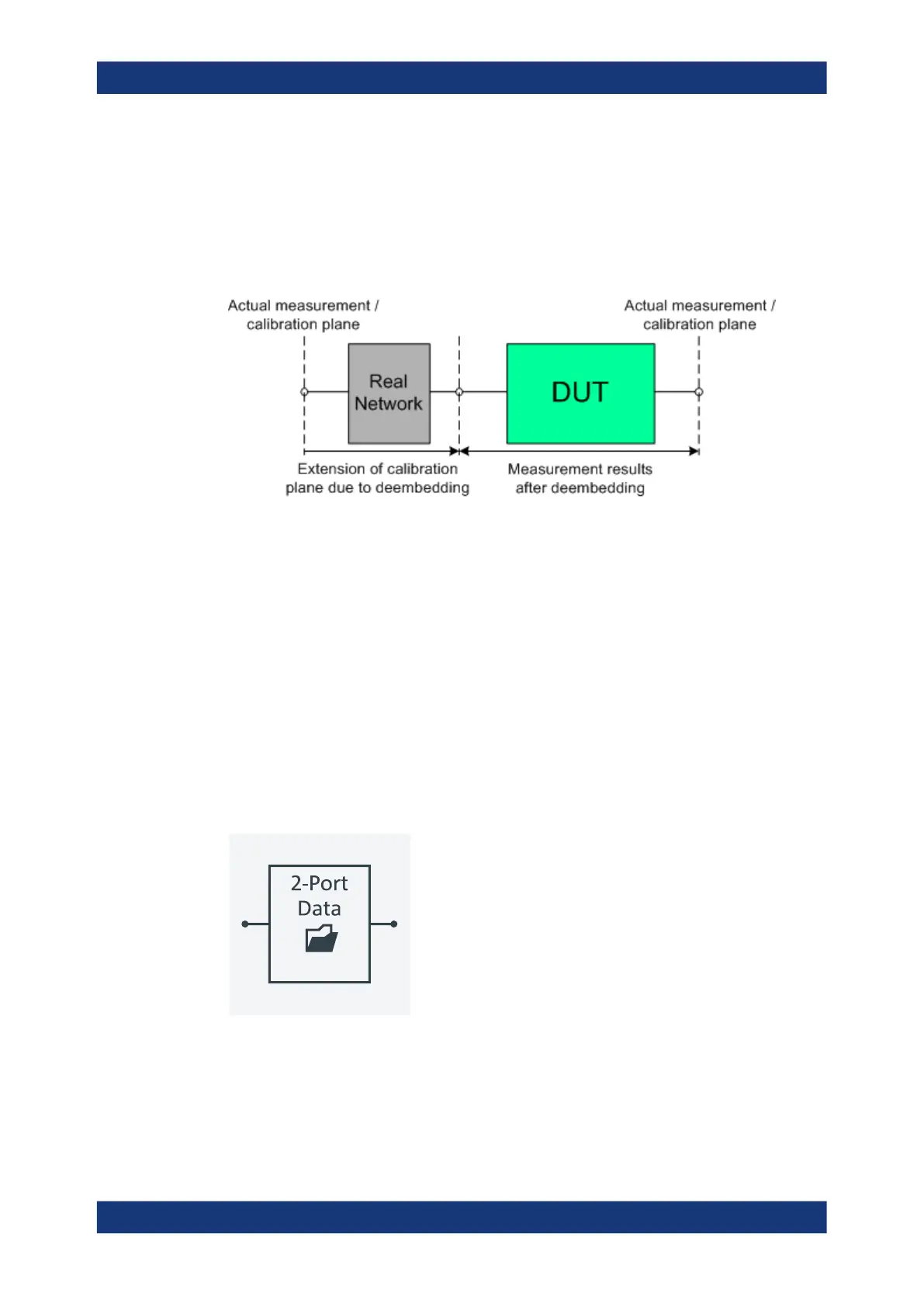
To be numerically removed, the real network must be described by a set of S-parame-
ters or by an equivalent circuit of lumped elements. Deembedding the DUT effectively
extends the calibration plane towards the DUT ports, enabling a realistic evaluation of
the DUT without the distorting network. Deembedding can be combined with length off-
set parameters; see Chapter 5.6.1, "Offset Parameters", on page 182.
The simplest case of single port deembedding can be depicted as follows:
5.6.2.3 Circuit Models for 2-Port Networks
The lumped element 2-port transformation networks for (de-)embedding consist of the
following two basic circuit blocks:
●
a capacitor connected in parallel with a resistor
●
an inductor connected in series with a resistor
The 2-port transformation networks comprise all possible combinations of 2 basic
blocks, where either one block represents a serial and the other a shunt element or
both represent shunt elements. In the default setting the resistors are not effective,
since the serial resistances are set to 0 Ω, the shunt resistances are set to 10 MΩ and
the shunt inductances are set to 0 Siemens.
The first network is defined by its S-parameters stored in an imported two-port Touch-
stone file (*.s2p). No additional parameters are required.
The following networks are composed of a serial capacitance C or inductance L (as
seen from the test port), followed by a shunt L or C. They are named
Serial C, Shunt L / Serial L, Shunt C / Serial C, Shunt C /
Serial L, Shunt L.
Offset Parameters and De-/Embedding