GUI Reference
R&S
®
ZNB/ZNBT
284User Manual 1173.9163.02 ─ 55
Stability
Selects a stability factor as a measured quantity for the active trace. The stability factor
calculation is based on 2-port reflection and transmission S-parameters so that the
input and output port numbers must be different. The pull-down list contains all possi-
ble physical (single-ended) port combinations. For an analyzer with n ports, provides n
* (n – 1) stability parameters.
Stability parameters are expressed as "K
<out><in>
", "μ1
<out><in>
", and "μ2
<out><in>
", where
<out> and <in> denote the logical output and input port numbers of the DUT.
Remote command:
CALCulate<Ch>:PARameter:MEASure "<Trace_Name>", "KFAC21" |
"MUF121" | "MUF221" | ...
CALCulate<Ch>:PARameter:SDEFine "<Trace_Name>", "KFAC21" |
"MUF121" | "MUF221" | ...
μ1 21/μ2 21/K 21
Selects one of the standard 2-port stability factors as a measured quantity for the
active trace. These buttons are enabled if none of the logical ports 1 and 2 is defined
as a balanced port.
Remote command:
CALCulate<Ch>:PARameter:MEASure "<Trace_Name>", "MUF121" |
"MUF221" | "KFAC21"
CALCulate<Ch>:PARameter:SDEFine "<Trace_Name>", "MUF121" |
"MUF221" | "KFAC21"
Balanced Ports...
Opens a dialog to define a balanced port configuration.
See Chapter 6.2.1.3, "Balanced Ports Dialog", on page 260.
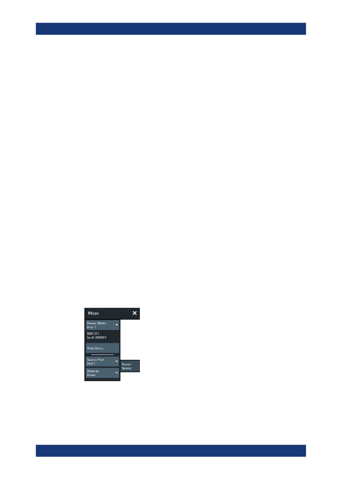
6.2.10 Power Sensor Tab
Allows you to set up and perform measurements using external power sensors.
The standard test setup for a "Power Sensor" measurement involves one analyzer
source port and a power sensor. The power sensor is connected to the VNA (e.g. to
the analyzer's USB port) and provides scalar wave quantity results. See Chap-
ter 5.7.25, "External Power Meters", on page 241.
Meas Softtool

 Loading...


