Annexes
R&S
®
ZNB/ZNBT
1428User Manual 1173.9163.02 ─ 55
Command Meaning Effect on the instrument
@LOC Go to Local Transition to the "local" state (manual control).
@REM Go to Remote Transition to the "remote" state (remote control).
11.3.3 GPIB Interface
The R&S ZNB/ZNBT can be equipped with a GPIB (IEC/IEEE) bus interface (option
R&S ZNB/ZNBT-B10. The interface connector labeled "GPIB" is located on the rear
panel of the instrument. The GPIB bus interface is intended for remote control of the
R&S ZNB/ZNBT from a controller.
Characteristics of the interface
●
8-bit parallel data transfer
●
Bidirectional data transfer
●
Three-line handshake
●
High data transfer rate of max. 1 MByte/s
●
Up to 15 devices can be connected
●
Wired OR if several instruments are connected in parallel
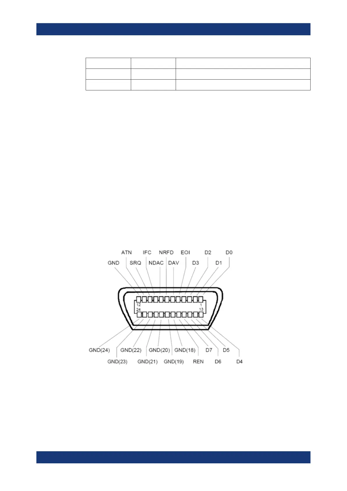
Pin assignment
Bus lines
●
Data bus with 8 lines D0 to D7:
The transmission is bit-parallel and byte-serial in the ASCII/ISO code. D0 is the
least significant bit, D7 the most significant bit.
●
Control bus with five lines:
Interfaces and Connectors

 Loading...


