Getting Started
R&S
®
ZNB/ZNBT
43User Manual 1173.9163.02 ─ 55
Input levels, EMC
The maximum input levels and voltages of the input connectors at the front and rear
panel must not be exceeded. Match signals with 50 Ω to comply with EMC directives.
See also Chapter 4.1.5, "EMI Suppression", on page 20.
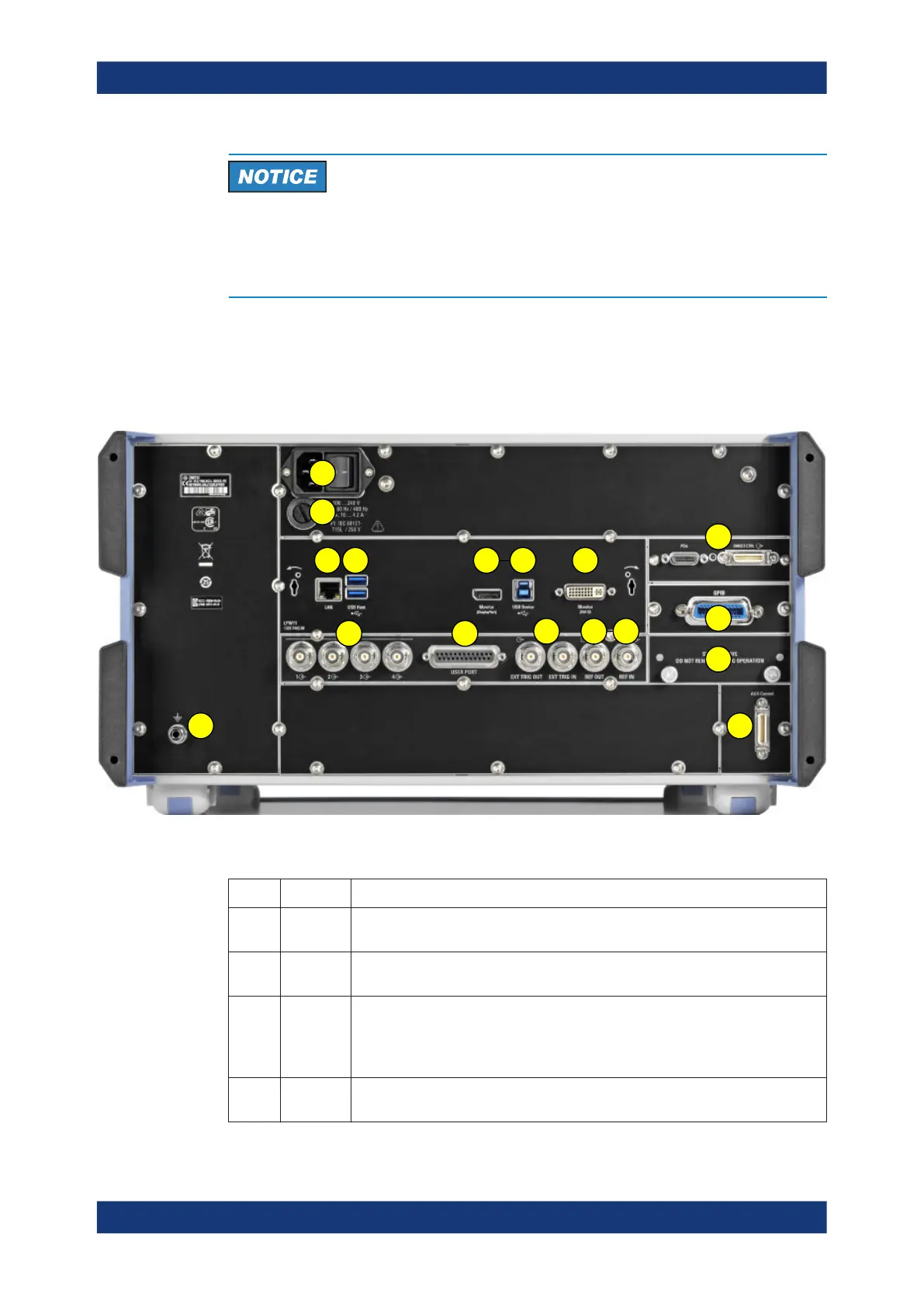
4.2.4 Rear Panel R&S ZNBT
This section gives an overview of the rear panel controls and connectors of the
R&S ZNBT.
1
2
12
3 4 5
8
13
11
15
76
9 10
14
16
17
Figure 4-5: R&S
ZNBT rear view
Table 4-4: Rear panel connectors available on all instruments
Index Label Description
1 (Power
I/O)
Power on/off switch, see Chapter 4.1.7, "Starting the Analyzer and Shutting Down",
on page 22
2 (Fuse
holder)
Fuse holder, see Chapter 11.4.3, "Replacing Fuses", on page 1442
3 LAN RJ-45 connector to integrate the instrument to a Local Area Network, primarily for
remote control purposes; see Chapter 4.1.12.1, "Assigning an IP Address",
on page 28.
See also Chapter 11.3.2, "LAN Interface", on page 1427.
4 USB /
USB Host
Two additional type A USB 3.0 host connectors; similar functionality as the type A
USB host connectors on the front panel (see "USB Connectors" on page 40).
Instrument Tour

 Loading...


