Getting Started
R&S
®
ZNB/ZNBT
72User Manual 1173.9163.02 ─ 55
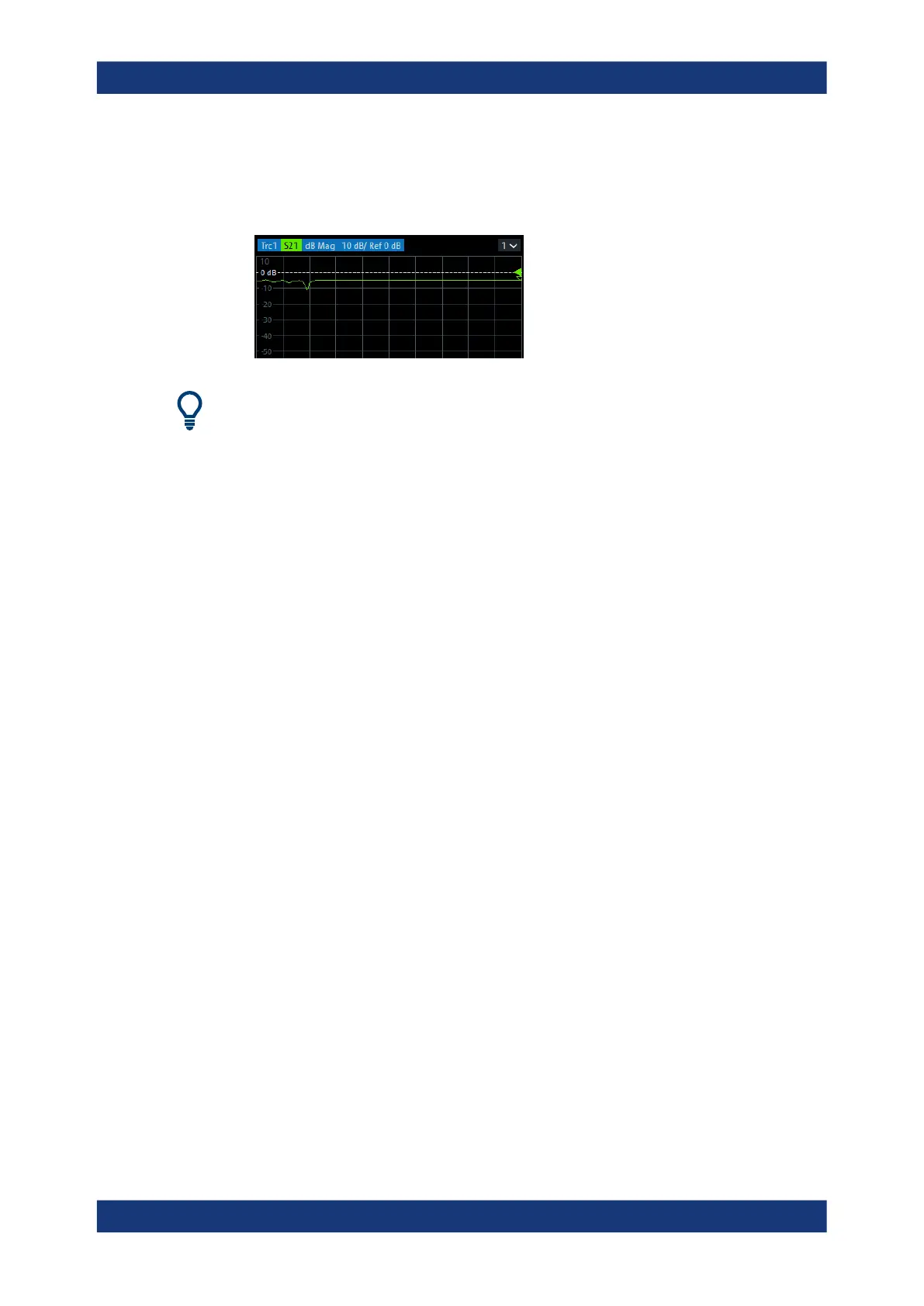
3. Use the [PRESET] key to restore a well-defined instrument state.
The analyzer is now set to its default state. The default measured quantity is the
transmission S-parameter S
21
.
Select TRACE – [TRACE CONFIG] and use the control elements in the "Traces" soft-
tool tab if you wish to create additional traces and diagrams.
4.4.1.2 Selecting the Sweep Range and Other Parameters
After a system preset the display shows a diagram with a dB magnitude scale, and the
S-parameter S
21
is selected as a measured quantity. This S-parameter is the forward
transmission coefficient of the DUT. It is defined as the ratio of the transmitted wave at
the DUT's output port (port no. 2) to the incident wave at the DUT's input port (port no.
1).
The R&S ZNB/ZNBT automatically adjusts its internal source and receiver to the
selected measured quantities: For an S
21
measurement, a stimulus signal (termed a
1
)
is transmitted at the analyzer port no. 1; the transmitted wave (termed b
2
) is measured
at port 2. The stimulus signal from the analyzer port no. 2 is not needed except for
some calibration types.
By default the sweep range is set to the frequency range of the analyzer, which can be
unsuitable for your DUT. The following procedure shows you how to configure a
smaller sweep range.
1. Select STIMULUS – [START] and set the "Start Frequency" to the lowest fre-
quency you want to measure (e.g. 1.77 GHz). For convenient numeric entry, open
the "Numeric Editor" (see Chapter 4.3.5.2, "Using the Numeric Editor",
on page 62).
Tip: If you use the DATA ENTRY keys at the front panel for data entry (R&S ZNB
only), type [1][.][7][7] and terminate the entry with the [G/n] key.
Refer to Chapter 4.3.5, "Entering Data", on page 61 to learn more about entering
numeric values and characters.
2. In the "Stop Frequency" input field, enter the highest frequency you want to mea-
sure (e.g. 2.5 GHz).
3. Select TRACE – [SCALE] > "Scale Values" and activate the "Auto Scale Trace"
function. The analyzer adjusts the scale of the diagram to fit in the entire S
21
trace,
leaving an appropriate display margin.
Performing Measurements