Concepts and Features
R&S
®
ZNB/ZNBT
91User Manual 1173.9163.02 ─ 55
5.2 Screen Elements
This section describes manual operation of the analyzer, including trace settings, mark-
ers and diagrams. For a description of the different quantities measured by the instru-
ment, refer to Chapter 5.3, "Measurement Results", on page 114.
5.2.1 Display Elements of a Diagram
The central part of the screen is occupied by one or more diagrams.
A diagram is simply a rectangular portion of the screen used to display traces. Dia-
grams are independent of trace and channel settings. A diagram can contain a practi-
cally unlimited number of traces which can be assigned to different channels.
Most diagram settings are arranged in the "Display" softtool (hardkey SYSTEM – [DIS-
PLAY]). To assign traces and channels to diagrams, use the control elements on the
"Trace Config" > "Traces" and "Channel Config" > "Channels" softtool tabs (hardkeys
TRACE – [TRACE CONFIG] and CHANNEL – [CHANNEL CONFIG]).
Diagrams can contain:
●
A title (optional)
●
The diagram number (or label)
●
Measurement results, in particular traces and marker values (optional)
●
An indication of the basic channel and trace settings
●
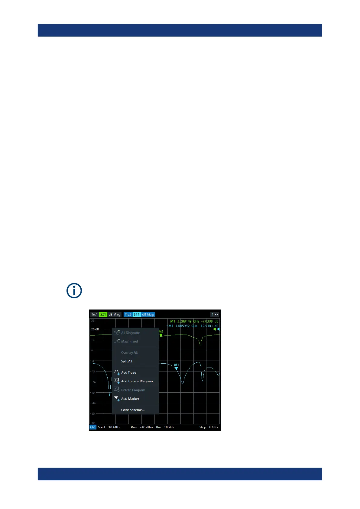
Context menus providing settings which are related to a particular display element
●
Error messages
The examples in this section have been taken from Cartesian diagrams. All other dia-
gram types provide the same display elements.
Screen Elements