Annexes
R&S
®
ZNB/ZNBT
1425User Manual 1173.9163.02 ─ 55
11.2 System Recovery
For instruments running Windows 10, the system drive is delivered with a recovery
partition that allows you to restore the original operating system image and firmware.
To access the recovery functionality, open the Windows control panel, select "Update &
Security" > "Recovery" > "Restart Now" and wait for the "R&S Recovery Environment"
to start.
You can also use the Recovery Tab of the "System Config" dialog to boot into the
recovery environment.
To restore the original operating system image and firmware, proceed as follows:
1. In the "R&S Recovery Environment" select "Factory Default Restore"
2. Wait for the reimaging process to complete
3. Reboot the instrument
After the restore, upgrade to the desired firmware version (see Chapter 11.1.2, "Firm-
ware Installation", on page 1424).
11.3 Interfaces and Connectors
This chapter provides a detailed description of the rear panel connectors of the
R&S ZNB/ZNBT. An overview of the available front and rear panel is given in the Get-
ting Started guide (see Chapter 4.2, "Instrument Tour", on page 32).
EMI Suppression
Notice the instructions in Chapter 4.1.5, "EMI Suppression", on page 20.
11.3.1 Rear Panel Connectors
The rear panel of the R&S ZNB/ZNBT provides various connectors for external devices
and control signals.
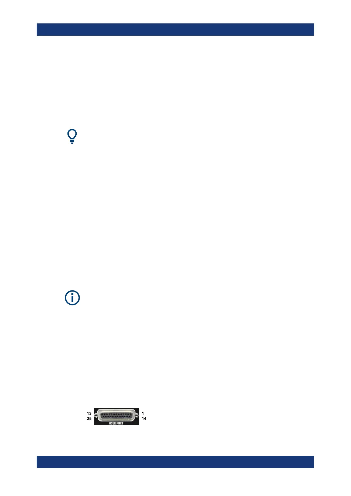
11.3.1.1 USER PORT
25-pole D-Sub connector used as an input and output for low-voltage (3.3 V) TTL con-
trol signals. Some of the lines can be configured (see CONTrol Commands and OUT-
Put Commands).
Interfaces and Connectors

 Loading...


