Getting Started
R&S
®
ZNB/ZNBT
40User Manual 1173.9163.02 ─ 55
– Error <error code>: severe errors (e.g. FW boot errors, HW errors)
●
Control mode:
– "Local": manual interaction (e.g. via Remote Desktop)
– "Remote": remote control (using a script) via a LAN or GPIB connection
USB Connectors
Two USB 2.0 connectors of type A (master USB) are provided on the front panel. They
can be used to connect:
●
External PC accessories such as mouse or other pointing devices, a keyboard,
printer or external storage device (USB stick, CD-ROM drive etc.).
●
External measurement equipment such as a calibration unit, power meter, signal
generator or switch matrix.
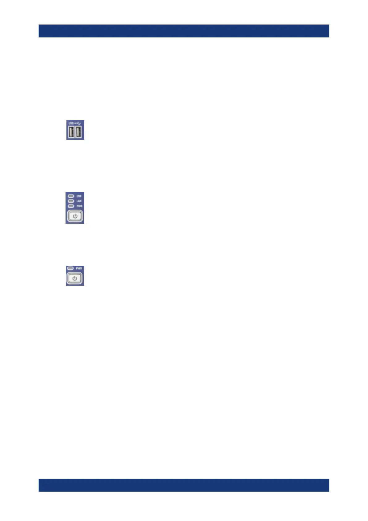
LED controls
Above the standby toggle switch some LEDs indicate various status information:
●
[ERR]: operation state; if an error occurs, the LED lights up red; for more informa-
tion on errors and troubleshooting see the R&S ZNB/ZNBT User Manual
●
[LAN]: LAN error occurred
●
[PWR]: power state (ready/standby); see Chapter 4.1.8, "Standby and Ready
State", on page 23
Standby key
The standby key is located at the lower right-hand corner of the front panel. It serves
two main purposes:
●
Toggle between standby and ready state; see Chapter 4.1.8, "Standby and Ready
State", on page 23.
●
Shut down the instrument; see Chapter 4.1.7, "Starting the Analyzer and Shutting
Down", on page 22.
4.2.3 Rear Panel R&S ZNB
This section gives an overview of the rear panel controls and connectors of the net-
work analyzer.
Instrument Tour