Concepts and Features
R&S
®
ZNB/ZNBT
81User Manual 1173.9163.02 ─ 55
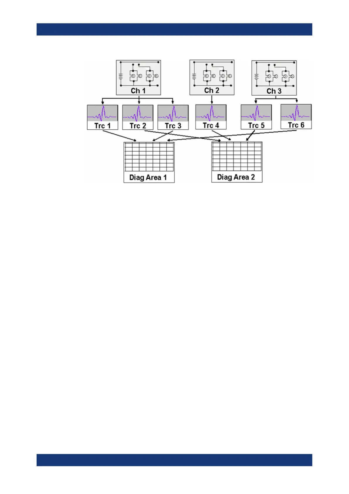
5.1.3.1 Trace Settings
The trace settings specify the mathematical operations used to obtain traces from the
measured or stored data. They can be divided into several main groups:
●
Selection of the measured quantity (S-parameters, wave quantities, ratios, impe-
dances,...)
●
Conversion into the appropriate display format and selection of the diagram type
●
Scaling of the diagram and selection of the traces associated to the same channel
●
Readout and search of particular values on the trace by means of markers
●
Limit check
The trace settings can be accessed via the keys in the TRACE section of the (virtual)
hardkey panel. They complement the Channel Settings accessible via the STIMULUS
and CHANNEL sections.
Each trace is assigned to a channel. The channel settings apply to all traces of the
channel.
5.1.3.2 Channel Settings
A channel contains hardware-related settings which specify how the network analyzer
collects data. The channel settings can be divided into three main groups:
●
Description of the test setup (power of the internal source, IF filter bandwidth, port
configuration, receiver step attenuators, ...)
●
Control of the measurement process (sweep, trigger, averaging, ...)
●
Correction data (calibration, offset, ...)
The channel settings can be accessed via the STIMULUS and CHANNEL sections of
the (virtual) hardkey panel.
Basic Concepts

 Loading...


