Getting Started
R&S
®
ZNB/ZNBT
37User Manual 1173.9163.02 ─ 55
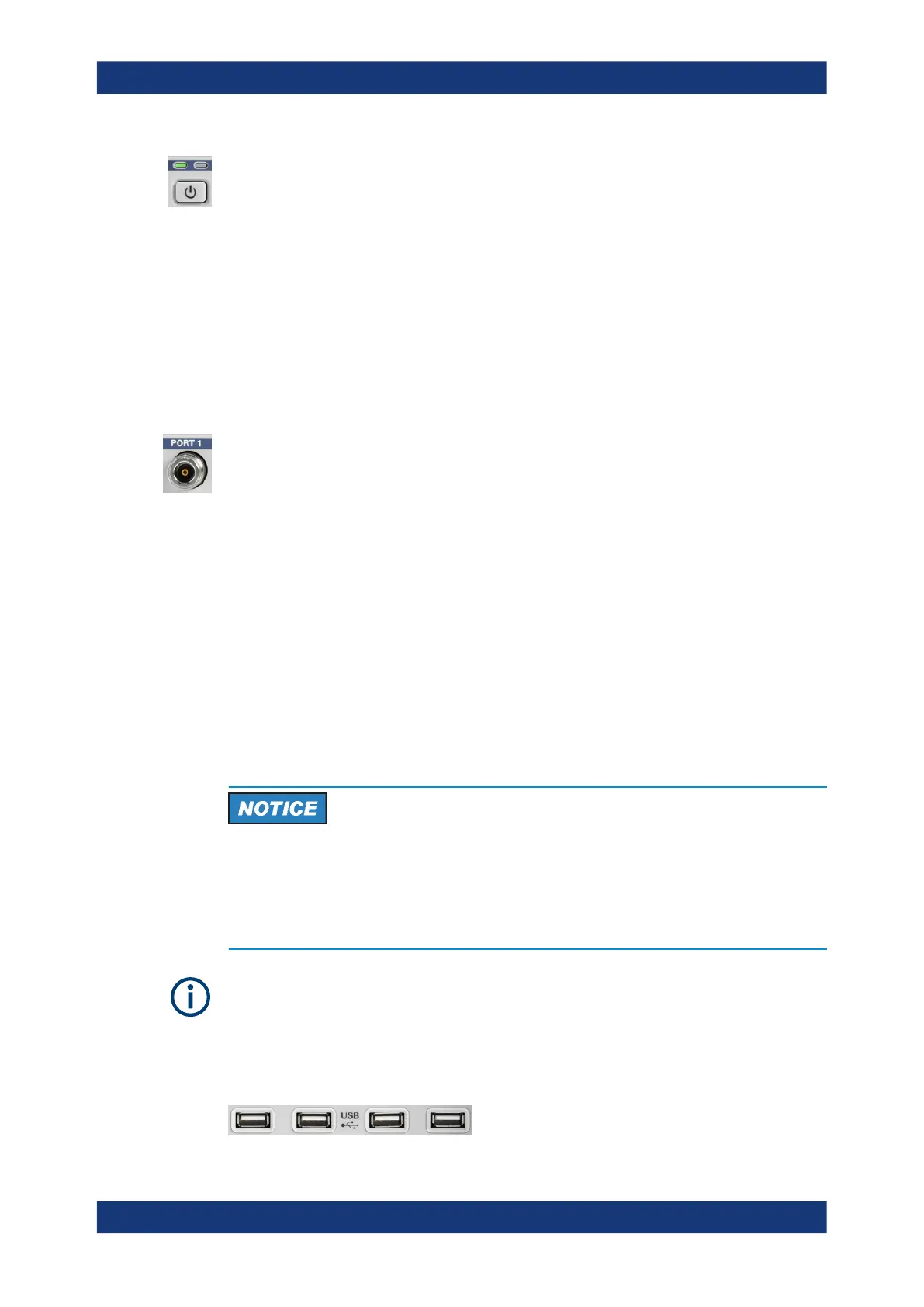
The standby toggle switch is located in the bottom left corner of the front panel.
The key serves two main purposes:
●
Toggle between standby and ready state; see Chapter 4.1.8, "Standby and Ready
State", on page 23.
●
Shut down the instrument; see Chapter 4.1.7, "Starting the Analyzer and Shutting
Down", on page 22.
4.2.1.7 Front Panel Connectors
The test ports and four USB connectors are located on the front panel of the R&S ZNB.
Test Ports
Numbered connectors:
●
type N female for R&S ZNB4 and R&S ZNB8
●
3.5 mm male for R&S ZNB20
●
2.92 mm (K) male for R&S ZNB40
The test ports serve as outputs for the RF stimulus signal and as inputs for the mea-
sured RF signals from the DUT (response signals).
●
With a single test port, it is possible to generate a stimulus signal and measure the
response signal in reflection. For a measurement example, refer to Chapter 4.4.2,
"Reflection S-Parameter Measurement", on page 77.
●
With more than one test port, it is possible to perform full two-port, 3-port, ... , or n-
port measurements; see Chapter 5.3.1, "S-Parameters", on page 114.
In the standard R&S ZNB configuration, all test ports are supplied by a common
source. Four-port instruments are available with an optional second source. For the
R&S ZNBT, an internal second source is automatically added if the instrument is
equipped with 12 ports or more.
Maximum input levels
The maximum input levels at all test ports according to the front panel labeling or the
data sheet must not be exceeded.
In addition, the maximum input voltages of the other input connectors at the rear panel
must not be exceeded.
Use a torque wrench when screwing RF cables on the test port connectors.
USB Connectors
Four high-speed Universal Serial Bus connectors of type A (master USB).
Instrument Tour

 Loading...


