Getting Started
R&S
®
ZNB/ZNBT
21User Manual 1173.9163.02 ─ 55
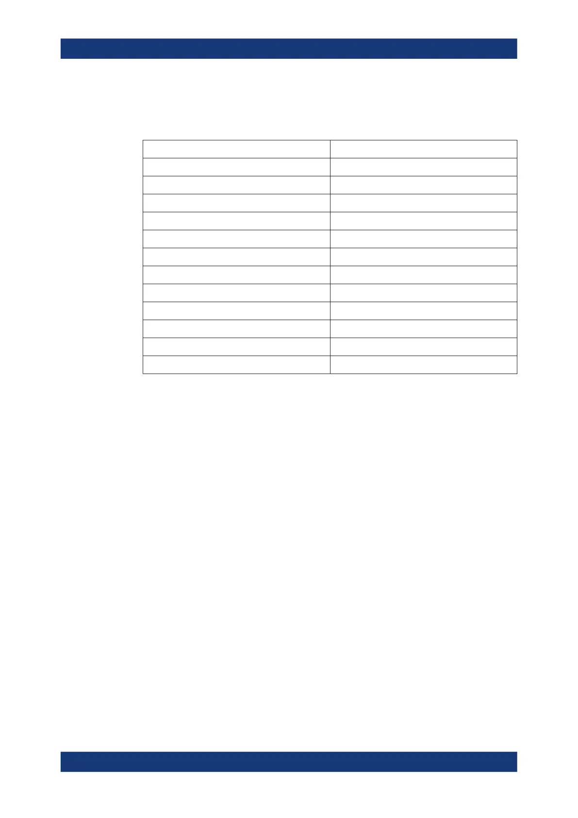
Regarding length and quality, the following requirements have to be met for cable that
are directly connected to the R&S ZNB/ZNBT:
Table 4-1: Cable Requirements
Cable Type (Connector) Requirement
RF cables (PORT 1, ..., PORT N) Double shielded
BNC cables (various) Double shielded
DB-25 (USER PORT) Double shielded
Digital I/Q (DIRECT CTRL, AUX CONTROL) R&S order no. 1402.4990.00 only
GPIB Standard cable
Handler I/O Standard cable
RFFE/GPIO R&S ZN-Z25 (order no. 1334.3424.02) only
DisplayPort (Monitor) Standard cable
DVI-D (Monitor) 2 ferrite cores
LAN At least CAT6, S/FTP
PCIe Standard cable
USB Standard cables, length ≤ 3m
4.1.6 Connecting the Analyzer to the AC Supply
The network analyzer is automatically adapted to the AC supply voltage, which must
be in the range of 100 V to 240 V at 50 Hz to 60 Hz. A line frequency of 400 Hz is also
supported.
The mains connector is located in the upper part of the rear panel (see Chapter 4.2.3,
"Rear Panel R&S ZNB", on page 40 or Chapter 4.2.4, "Rear Panel R&S ZNBT",
on page 43).
► Connect the network analyzer to the AC power source using the AC power cable
delivered with the instrument.
The maximum power consumption and the typical power consumption of the individual
analyzer models are listed in the data sheet.
The R&S ZNBT is protected by a fuse located below the AC power switch; see Chap-
ter 11.4.3, "Replacing Fuses", on page 1442. There are no such fuses on the R&S ZNB.
Putting the Analyzer into Operation

 Loading...


