Getting Started
R&S
®
ZNB/ZNBT
41User Manual 1173.9163.02 ─ 55
1
2
12
3 4 5
8
13
11
14
7
6
9 10
15
16
17
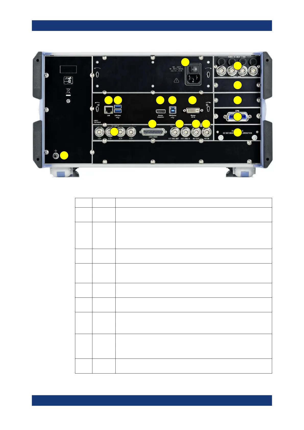
Figure 4-4: R&S
ZNB rear view
Table 4-2: Rear panel connectors available on all instruments
Index Label Description
1 (Power
I/O)
Power on / off switch, see Chapter 4.1.7, "Starting the Analyzer and Shutting Down",
on page 22
2 LAN RJ-45 connector to integrate the instrument to a Local Area Network, primarily for
remote control purposes; see Chapter 4.1.12.1, "Assigning an IP Address",
on page 28.
See also Chapter 11.3.2, "LAN Interface", on page 1427.
3 USB /
USB Host
Two additional type A USB 3.0 host connectors; similar functionality as the USB con-
nectors on the front panel (see "USB Connectors" on page 37).
4 Monitor
(Display-
Port)
External monitor connector (DisplayPort); see Chapter 4.1.9.1, "Connecting a Moni-
tor", on page 24.
5 USB
Device
Type B USB 3.0 device (slave) connector for remote control of the instrument (see
Chapter 4.1.9.6, "Connecting a USB Cable for Remote Control", on page 26)
6 Monitor
(DVI-D)
External monitor connector (DVI-D); see Chapter 4.1.9.1, "Connecting a Monitor",
on page 24.
7 USER
PORT
25-pin D-Sub connector used as an input and output for low-voltage (3.3 V) TTL
control signals
See Chapter 11.3.1.1, "USER PORT", on page 1425.
8 EXT TRIG
IN / EXT
TRIG
OUT
Two BNC connectors for 5 V TTL external trigger signals
See Chapter 6.10.3, "Trigger Tab", on page 405.
9 REF OUT BNC output for the internal reference frequency of the R&S ZNB. Use this connector
to synchronize other instruments to the analyzer.
Instrument Tour