Getting Started
R&S
®
ZNB/ZNBT
42User Manual 1173.9163.02 ─ 55
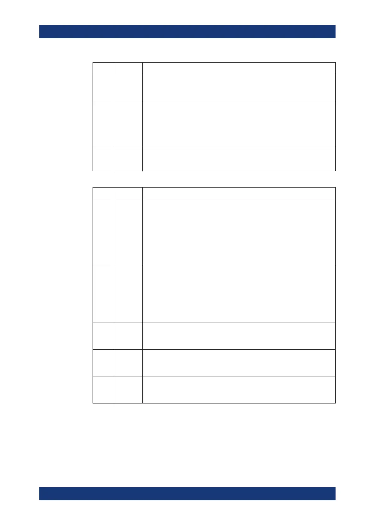
Index Label Description
10 REF IN BNC input for an external reference frequency. Use this connector to synchronize
the R&S ZNB to another device.
See Chapter 6.17.2, "Freq. Ref. Tab", on page 714.
11 (System
drive)
Contains the removable system drive of the R&S ZNB, containing all software
(including the operating system and the VNA application) and data. Do not remove
the system drive during operation.
Option R&S ZNB-B19 provides an additional removable system drive (including
operating system and firmware). See Chapter 5.7.19, "Additional Removable System
Drive", on page 235.
12 (Ground
connector)
The ground connector provides the ground of the analyzer's supply voltage. Use this
connector for ESD protection; see "Instrument damage caused by electrostatic dis-
charge" on page 19.
Table 4-3: Optional rear panel connectors
Index Label Description
13 Bias Tees
or
RFFE -
GPIO
Interface
This slot can be equipped with one of the following options:
●
R&S ZNB-B1, "Bias Tees", providing two or four additional BNC inputs labeled
BIAS 1 ... 4 (for two-port or four-port analyzers). The inputs can be used to
apply an external DC voltage (bias) to the test ports. For fuse replacement,
refer to Chapter 11.4.3, "Replacing Fuses", on page 1442.
●
R&S ZN-B15 "RFFE - GPIO Interface".
25-pin female connector, providing:
– 2 independent RF Front-End (RFFE) interfaces according to the MIPI® Alli-
ance "System Power Management Interface Specification".
– 10 General Purpose Input/Output (GPIO) pins.
14 Device
Control
Option R&S ZNB-B12 "Device Control" provides a PCIe and a Direct Control con-
nector.
See Chapter 5.7.16, "Device Control", on page 233.
The Direct Control interface enables direct connections between the VNA measure-
ment bus and one or more extension devices, such as:
●
An external RFFE GPIO interface R&S ZN-Z15.
●
Switch matrices R&S ZN-Z8x.
●
Multiport calibration units R&S ZN-Z154.
15 Handler
I/O
Option R&S ZN-B14, Handler I/O (Universal Interface), providing a Centronics 36
input/output connector.
See Chapter 5.7.17, "Handler I/O (Universal Interface)", on page 233.
16 GPIB Option R&S ZNB-B10 provides a GPIB bus connector according to standard IEEE
488 / IEC 625.
See Chapter 11.3.3, "GPIB Interface", on page 1428.
17 DC INPUT Option R&S ZNB-B81"DC Inputs" provides four BNC inputs for DC measurements
(adjustable to different voltage ranges).
See Chapter 6.2.11, "DC Tab", on page 285.
Instrument Tour

 Loading...


