Concepts and Features
R&S
®
ZNB/ZNBT
216User Manual 1173.9163.02 ─ 55
VNA
1 2
RF
LO
IF
f
IF, up
= f
RF
+ f
LO
f
IF, down
= | f
RF
- f
LO
|
In this example, the transmission parameter S
21
corresponds to the mixer's conversion
gain.
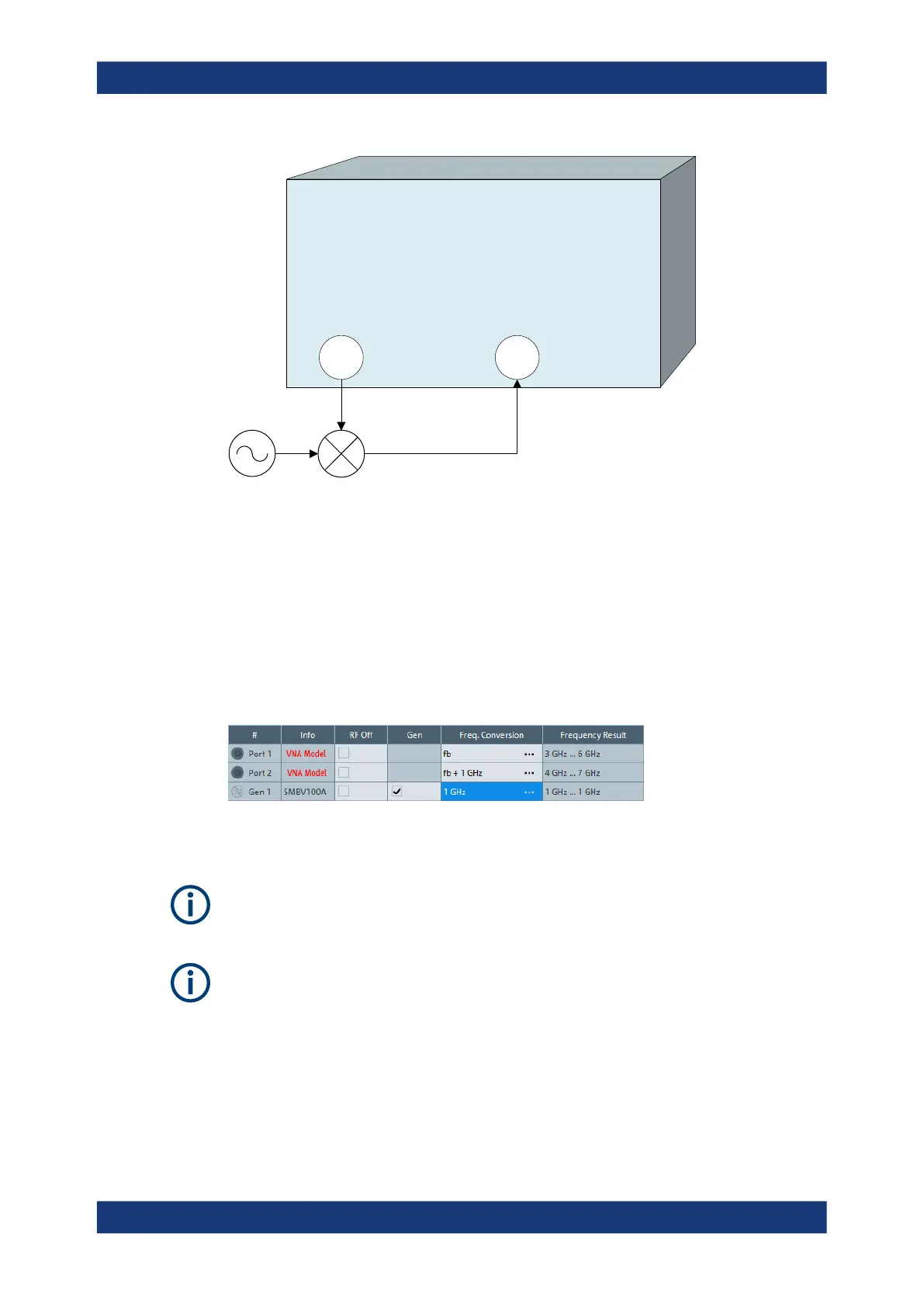
Before measuring, the port frequencies must be set appropriately. In the port configura-
tion table (CHANNEL – [CHANNEL CONFIG] > "Port Config" > "Port Settings..." > "Arb
Frequency"), the (source) frequency of Port 1 is set to the desired RF frequency (here:
the channel base frequency/sweep range f
b
). An external generator provides a fixed
stimulus signal at 1 GHz. To measure the up-converted IF signal, the (receive) fre-
quency at Port 2 is set to f
b
+ 1 GHz.
Independent source powers for Port 1 and Gen1 can be configured in addition, if so
desired.
Arbitrary Power Configuration
Arbitrary power configuration is also part of option R&S ZNB/ZNBT-K4.
Internal Second Source
If an internal second source is available, the mixer measurements outlined above (and
many other measurements) can be performed without an additional external generator;
see Chapter 5.7.13, "Internal Second Source", on page 232. However, be aware of the
limited source connectivity (described there).
Optional Extensions and Accessories

 Loading...


