Concepts and Features
R&S
®
ZNB/ZNBT
219User Manual 1173.9163.02 ─ 55
signals) or by an external generator. A test setup with two mixers involves two inde-
pendent LO signals at both mixers.
●
The IF signal is the mixer output signal (mixing product), which is at one of the fol-
lowing conversion frequencies: IF = LO + RF or IF = |LO – RF|, i.e. LO – RF (for
LO > RF) or IF = RF – LO (for RF > LO). The IF frequency is selected in the "Fre-
quencies" dialog. A test setup with two mixers involves two independent conver-
sion settings.
The signal description above, with the swept RF signal and the LO signal at a fixed fre-
quency, corresponds to the default configuration. In the "Frequencies" dialog, you can
select any of the signals as a "Sweep/CW" signal. You can set the frequency range for
this signal via "Start/Stop" or "CW Frequency". A second signal is at a "Fixed" fre-
quency, and the third at the calculated sum or difference frequency ("Auto").
The labeling of the complete diagrams depends on the sweep type.
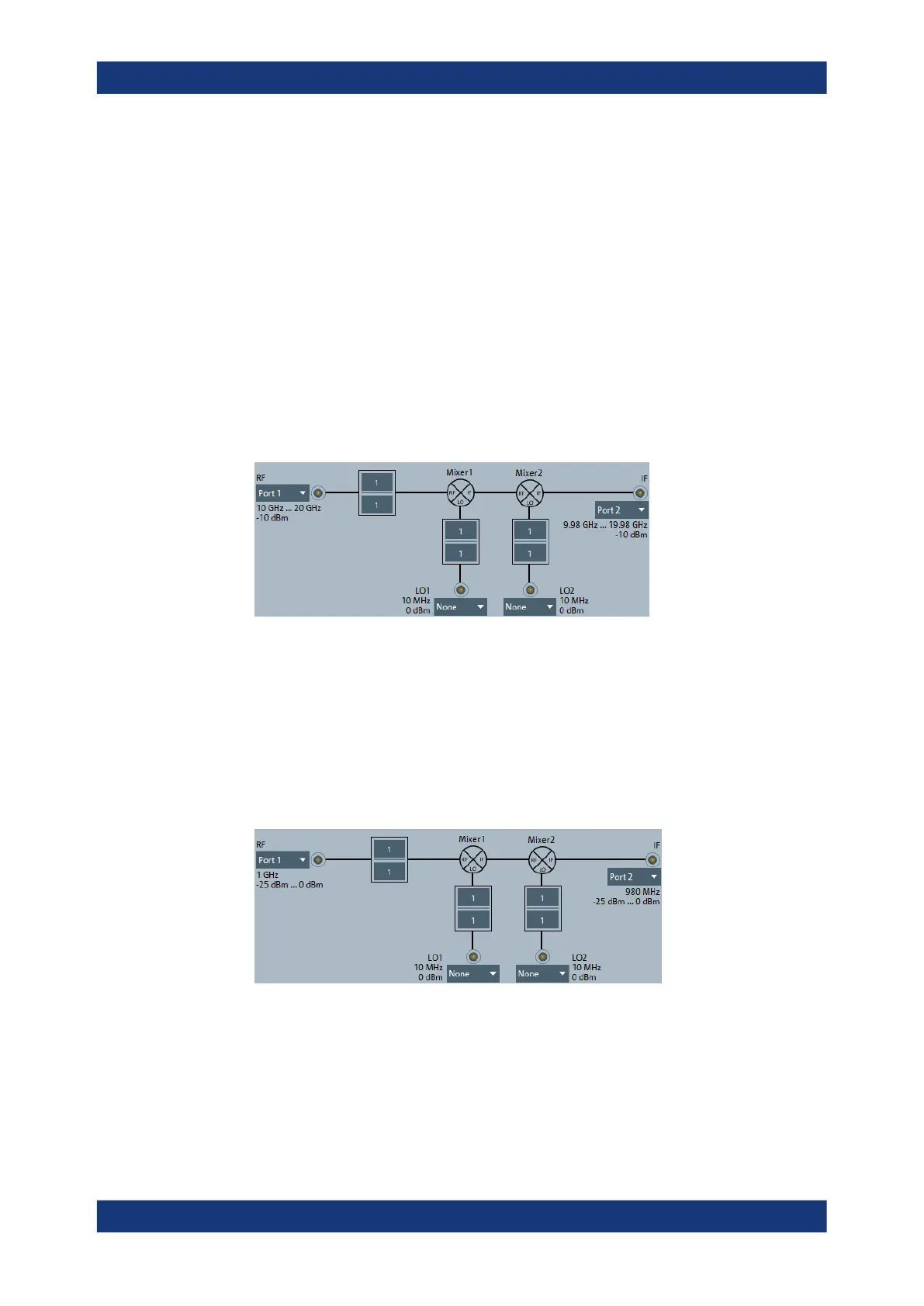
●
The following mixer signal diagram corresponds to a frequency sweep:
– RF signal (left side): Analyzer port number (e.g. Port 1), frequency sweep
range (or fixed frequency, if the LO signal is swept), CW power, frequency con-
version settings (1 / 1 denotes no conversion).
– LO signals (1 or 2, from below): Signal source (analyzer port or external gener-
ator), fixed power and frequency (or frequency sweep range, if the RF signal is
at fixed frequency), frequency conversion settings.
– IF signal (right side): Analyzer port number (e.g. Port 2), frequency range =
(sweep range + LO) or |sweep range – LO|, expected fixed power.
●
The following mixer signal diagram corresponds to a power sweep:
– RF signal (left side): Analyzer port number (e.g. Port 1), power sweep range or
fixed power, CW frequency, frequency conversion settings (1 / 1 denotes no
conversion).
– LO signals (1 or 2, from below): Signal source (analyzer port or external gener-
ator), fixed power or power sweep range, CW frequency, frequency conversion
settings.
Optional Extensions and Accessories

 Loading...


