Concepts and Features
R&S
®
ZNB/ZNBT
239User Manual 1173.9163.02 ─ 55
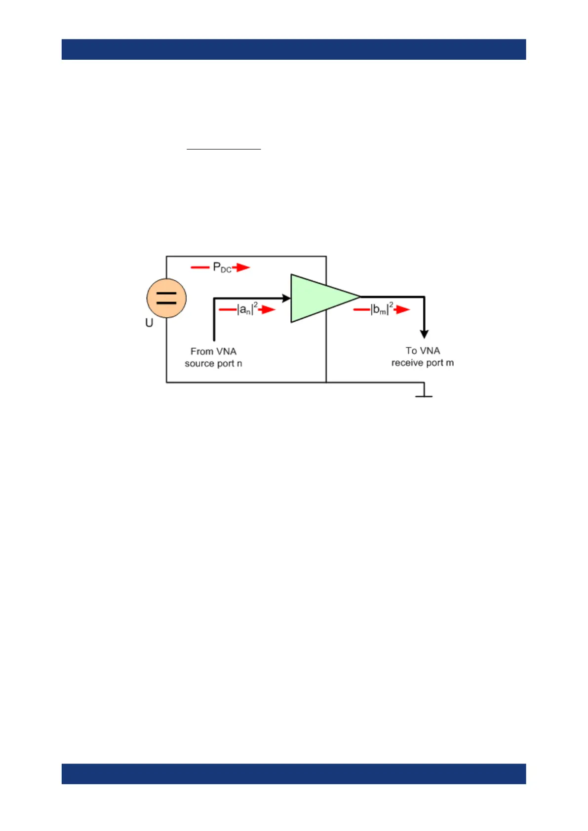
at the output of the DUT and the power of the incident wave a
n
at the input of the DUT;
hence:
DC
nm
P
ab
PAE
22
||||
Positive PAE values indicate a gain in the RF power, negative values an attenuation.
The PAE is always smaller than 1.
The PAE measurement is based on the standard test setup for forward S-parameter
measurements on a 2-port DUT. An additional measurement to determine the supplied
power P
DC
is required.
DC power measurement
For the R&S ZNB/ZNBT an external power supply is required to measure P
DC
.
The DC power P
DC
supplied to the DUT can be measured using one or two of the four
DC inputs DC INPUT 1...4 at the rear panel (option R&S ZVBx-B81). The Power
Added Efficiency dialog suggests different measurement types involving different test
setups. The measurement types depend on the properties of the DC power supply
(constant current I
0
or constant power U
0
) and an optional precision resistor R used to
measure the DC current. Depending on the measurement type, one or two of the val-
ues I
0
, U
0
, and/or R must be entered as parameters of the PAE calculation.
Optional Extensions and Accessories

 Loading...


