Command Reference
R&S
®
ZNB/ZNBT
903User Manual 1173.9163.02 ─ 55
Setting parameters:
<TraceName> Trace name, string variable, e.g. 'Trc4'. See "Rules for trace
names" in "Table Area" on page 305. Trace names must be
unique across all channels and diagrams.
If a trace with the selected trace name already exists, the ana-
lyzer behaves as follows: If the existing trace is assigned to the
same channel as the new trace, it is deleted. The new trace is
not automatically assigned to a diagram area; see note above.
If the existing trace is assigned to a different channel, no new
trace can be created. The analyzer returns an error message.
<Result> Measurement result (string variable), see table below.
Example:
CALC4:PAR:SDEF 'Ch4Tr1', 'S11'
Create channel 4 and a trace named Ch4Tr1 to measure the
input reflection coefficient S
11
.
DISP:WIND2:STAT ON
Create diagram area no. 2.
DISP:WIND2:TRAC:FEED 'CH4TR1'
Display the generated trace in diagram area no. 2.
Usage: Setting only
Manual operation: See "S-Parameter (selector)" on page 256
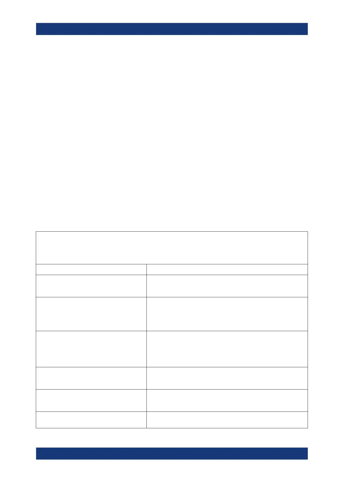
Table 8-4: String identifiers for measurement results
Note:
All port numbers in a result identifier refer to logical (=DUT) ports; to avoid ambiguities they must be represented by the same
number of digits (e.g. S21 or S0201). The valid port numbers are determined by the channel's logical port configuration
For details about the measurement results see Chapter 5.3, "Measurement Results", on page 114.
'S11' | 'S12' | ... | 'S0101' | ... Single-ended S-parameters S<i><j> for logical (DUT) ports <i> and <j>. To
avoid ambiguities, <i> and <j> must be specified with the same number of
digits.
'SCD11' | ... S-parameters involving balanced ports must be specified in the form
S<m_i><m_j><i><j>, where <m_i> and <m_j> denote the port modes of the
related logical ports <i> and <j>. In general, for the port modes <m_i><m_j>
all pairs of D (differential, balanced), C (common, balanced) and S (single-
ended, unbalanced) are allowed.
'Y11' | ... | 'YSS11' | ... | 'YCC11' | ... | 'YDD11' | 'Z11'
| ... | 'ZSS11' | ... | 'ZCC11' | ... | 'ZDD11' | ...
Short-circuit Y-parameters and open-circuit Z-parameters with port modes
and port numbers like for normal mode S-parameters.
Selecting a parameter Y...<n><m> or Z...<n><m> sets the range of logical
port numbers to be considered for the Y and Z-parameter measurement to
<n>:<m>.
'Y-S11' | ... | 'Y-SSS11' | ... | 'Y-SCC11' | ... | 'Y-
SDD11' | 'Z-S11' | ... | 'Z-SSS11' | ... | 'Z-SCC11' | ...
| 'Z-SDD11' | ...
S-parameters converted to matched-circuit admittances and impedances
with port modes and port numbers like for normal mode S-parameters. For
transmission parameters, this refers to series resistances.
'Y-S12SER' | 'Y-S12PAR' | ... | 'Z-S12SER' | 'Z-
S12PAR' | ...
Converted transmission admittances and impedances, calculated as ser-
iesChapter 5, "Concepts and Features", on page 79 or parallel admittances/
impedances.
'SHUNT-S12' | 'SHUNT-S13 | ... | 'SHUNT-S21' |
'SHUNT-S23' | ...
Converted impedances measured using shunt-thru method.
SCPI Command Reference

 Loading...


