Concepts and Features
R&S
®
ZNB/ZNBT
97User Manual 1173.9163.02 ─ 55
Marker Frmt"), or formatted individually (TRACE > [MARKER] > "Marker Props" >
"Marker Format").
The available marker formats are defined for all measured quantities and trace formats
(see Chapter 5.2.3.3, "Measured Quantities and Trace Formats", on page 113).
Essentially, a marker format is simply a conversion between points on a complex-val-
ued trace (the raw measurement data) and the respective target format. This must be
kept in mind when interpreting the results and physical units displayed.
The following table describes how a complex marker value z = x + jy is converted. It
makes use of the polar representation z = x + jy = |z| e
jφ(z)
, where
|z| = ( x
2
+ y
2
)
1/2
and φ(z) = arctan( y / x )
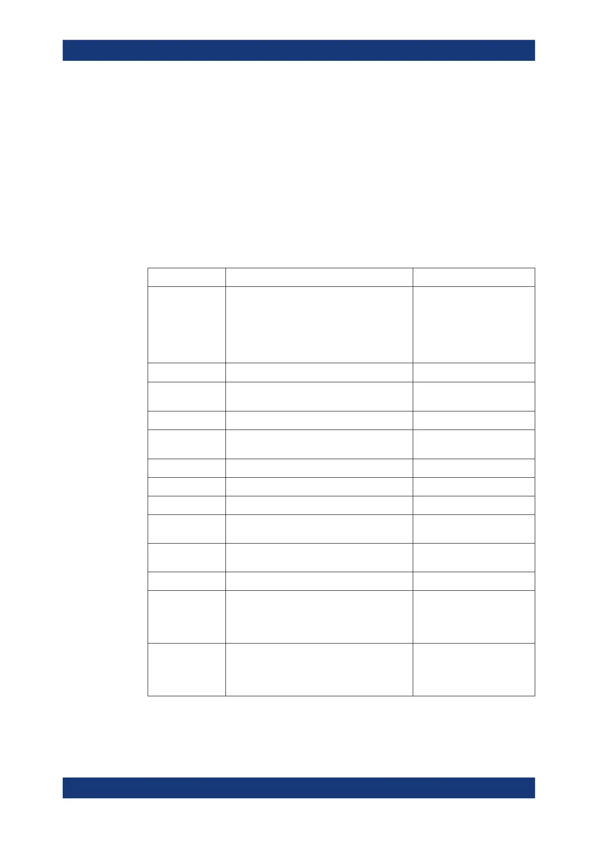
Table 5-2: Marker formats
Marker Format Description Formula
Default
●
For an individual marker, this means that
the marker is formatted according to the
default marker format of the related trace.
●
For a trace's default marker format, this
means that the default format is (dynamically)
adjusted according to the selected trace for-
mat.
–
Lin Mag Magnitude of z, unconverted
|z| = sqrt ( x
2
+ y
2
)
dB Mag Magnitude of z in dB
|z| = sqrt ( x
2
+ y
2
) dB Mag(z) =
20 * log|z| dB
Phase Phase of z φ (z) = arctan (y/x)
Delay Group delay, neg. derivative of the phase
response
*)
– dφ(z) / dω, where ω denotes
the stimulus frequency
Real Real part of z Re(z) = x
Imag Imaginary part of z Im(z) = y
SWR (Voltage) Standing Wave Ratio SWR = (1 + |z|) / (1 – |z|)
dB Mag Phase Magnitude of z in dB and phase in two lines 20 * log|z| dB arctan ( Im(z) /
Re(z) )
Lin Mag Phase Magnitude of z (unconverted) and phase in two
lines
|z| arctan ( Im(z) / Re(z) )
Real Imag Real and imaginary part of z in two lines x y
R + j X
or
R + j X series
***)
(Series) impedance:
Unnormalized (series) resistance, reactance, and
either inductance or capacitance, in three lines
(Smith diagram)
R
s
X
s
L
s
or C
s
**)
R + j X parallel
***)
Parallel impedance:
Unnormalized parallel resistance, reactance, and
either inductance or capacitance, in three lines
(Smith diagram)
R
p
X
p
L
p
or C
p
**)
Screen Elements

 Loading...


