Chapter 3
Theory of Operation
P/N 57150002, Revision 5.0 3 - 47 Trimble S, VX, SPS & RTS Service Manual
F
The PSM board also works as a connector board between the servo side cover, battery/radio side
cover, TCU attachment & Face 2 panel.
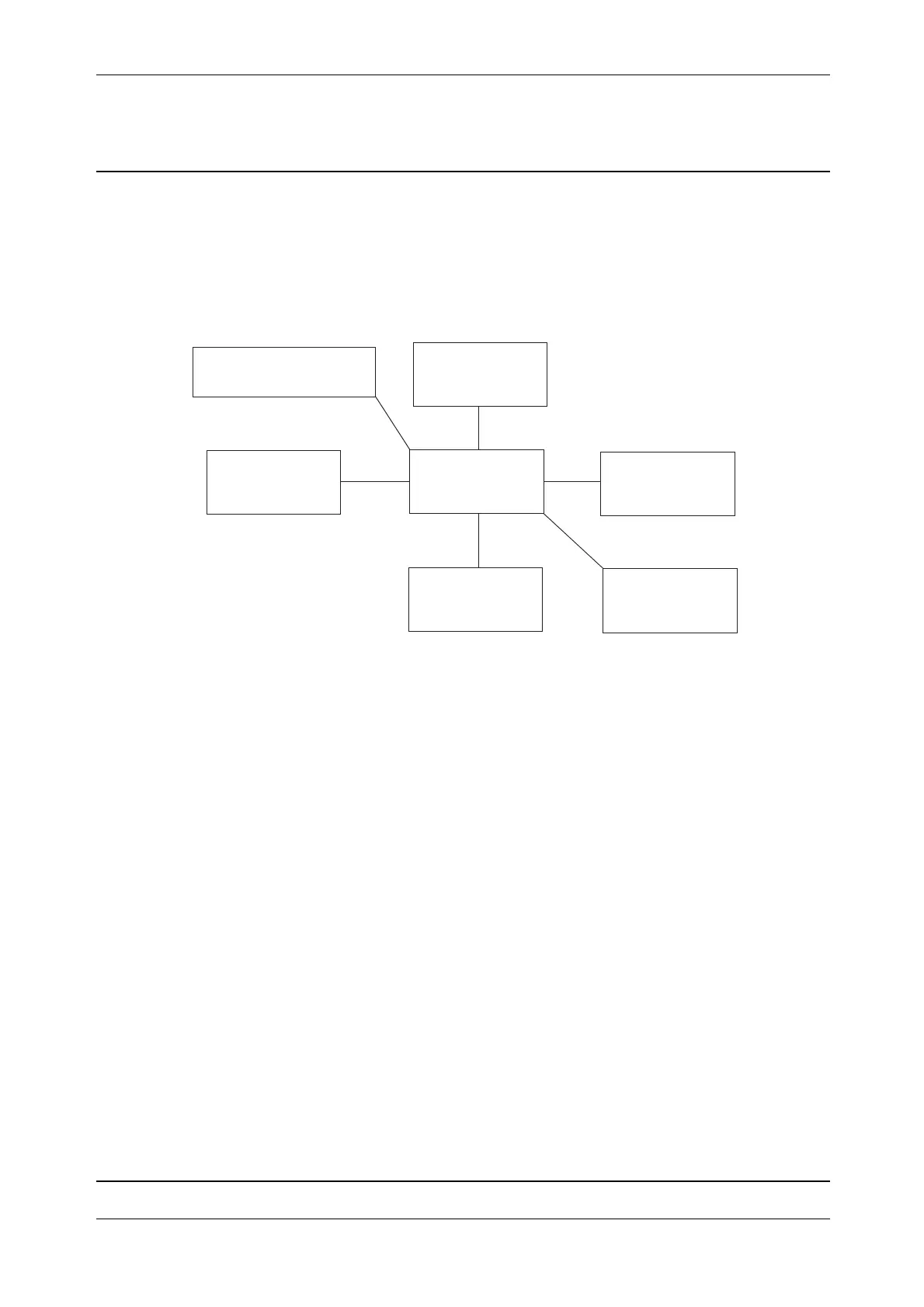
Functional diagram
Fig. 3-46 PSM functional diagram
The PSM cyclically checks the internal and external power sources and keeps the status internally.
At power up of the instrument the external source is used if it is good enough. The minimum input
voltage (internal battery or external power in) is 6.8V.
If a power source (internal battery or external power in) fails by disconnecting or if it drops below
6.8V, the PSM will switch immediately to another available power source.
A protection against destroying the batteries from deep discharge is provided.
In case an external power source supplies too high voltage, over 16 volts the instrument will not use
this power source. This status is reported and a warning is generated.
The PSM is responsible for control of the optional pressure and temperature sensor. The calibration
values of the sensors are stored in the PSM board. The PSM receives the calibration values when the
sensor is installed.
Service
Replacement of spare parts
• PSM board
PSM board
Temperature &
Face 2 panel
Radio / Battery
side cover
IPC board
Base unit
TCU attachment
Sliprings
pressure sensor