Chapter 3
Theory of Operation
P/N 57150002, Revision 5.0 3 - 19 Trimble S, VX, SPS & RTS Service Manual
F
The PCS function is equivalent to the POA/PAC & SRV boards in the Trimble 5600 series.
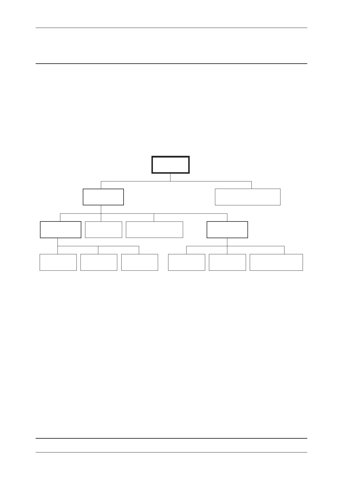
USB structure
IM communicates to all satellites/units direct or via a hub. There are three hubs in the USB structure,
one in the IPC board, one in the PSM board and one in the SFC board. These hubs helps IM to
communicate with more units.
IM is the host when communicating with internal units. When communicating via the foot connector
IM can be either host or device mode depending on the external unit.
Fig. 3-17 USB structure in the S6 instrument
Service
Maintenance
After replacement of IPC board:
• Update firmware, see page 6-31
• Initialize instrument data, see page 6-7
Replacement of spare parts
• IPC board
IM
Foot connector
PSM hub
PSM
PCS Tilt sensor
SFC hub
Radio TCU SFC Tracker
Distance unit
IPC hub