Chapter 3
Theory of Operation
Trimble S, VX, SPS & RTS Service Manual3 - 76 P/N 57150002, Revision 5.0
F
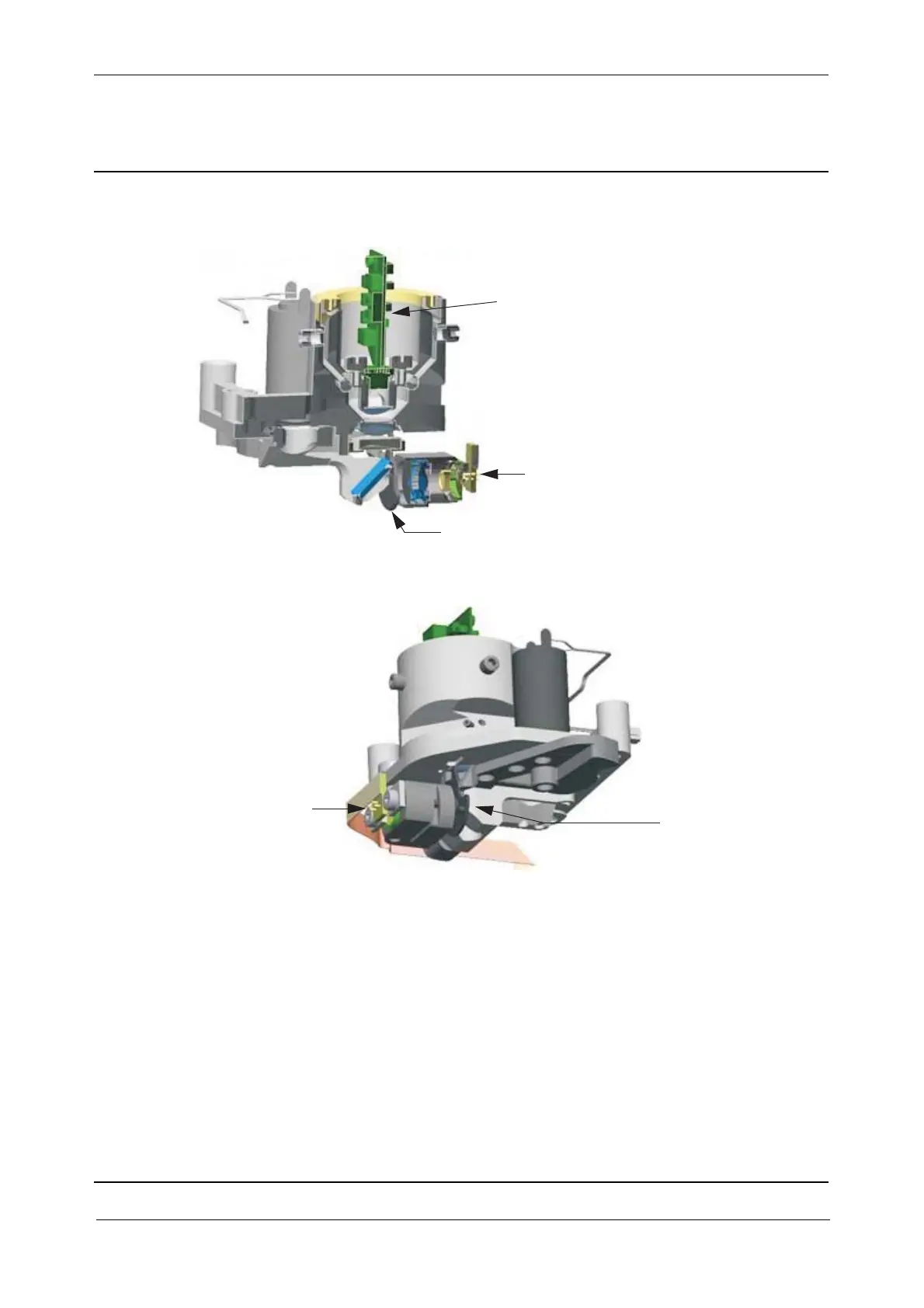
Fig. 3-68 Section view of transmitter unit
Fig. 3-69 Tracker transmitter and tracker shutter
Functional Block diagrams
All EDM functions are placed on 2 boards which are connected via a coax cable. The micro controller
receives and executes the commands from instrument manager, IM (IPC board).
IM controls the measure sequence, motors and laser pointer.
Laser drive board incl. laser diode
Tracker transmitter
Tracker shutter
Tracker transmitter
Tracker shutter