Chapter 3
Theory of Operation
Trimble S, VX, SPS & RTS Service Manual3 - 12 P/N 57150002, Revision 5.0
F
S6, S8, SPS & RTS models:
• Output power - 100mW
• Range - 1100m between instrument (1,8m antenna height) to robotic holder (1m antenna
height)
S3 Robotic model:
• Output power - 10mW, set by configuration number.)
• Range - 300m between instrument (1,8m antenna height) to TSC2 (1m antenna height)
Function description
The Georadio 2.4 uses the open ISM band on 2.4 GHz. It applies frequency hopping spread spectrum
technology. The radio meets FCC rules 15.247 and ETSI (European) 300.328 for worldwide license
free operation.
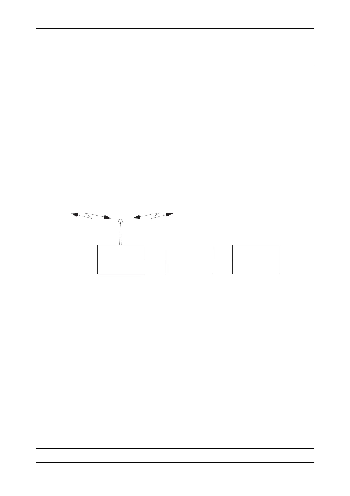
Fig. 3-11 Radio functional diagram
The radio side cover consists of a radio module and a modem board. The modem board operates as a
link between the radio module and the instrument.
The Radio side cover and External radio are identical but the modem board and radio configuration
is different.
Radio software and configuration
The radio can be configured for different country specific settings.
Radio module
The radio module is WIT2410 from Cirronet. It applies frequency hopping spread spectrum in the
frequency range 2401 to 2470 MHz. The radio handles both data and control at up to 115 Kb/s.
Antenna
The antenna connector on radio side cover and external radio is a reversed polarity TNC-RP-MMCX
connector.
Modem board - BRC board
The BRC board converts the radios RS232 signals to IPC’s USB communication. The board also
contains power supply/supervision, ESD protection.
Radio module
BRC board
IPC