Chapter 3
Theory of Operation
P/N 57150002, Revision 5.0 3 - 71 Trimble S, VX, SPS & RTS Service Manual
F
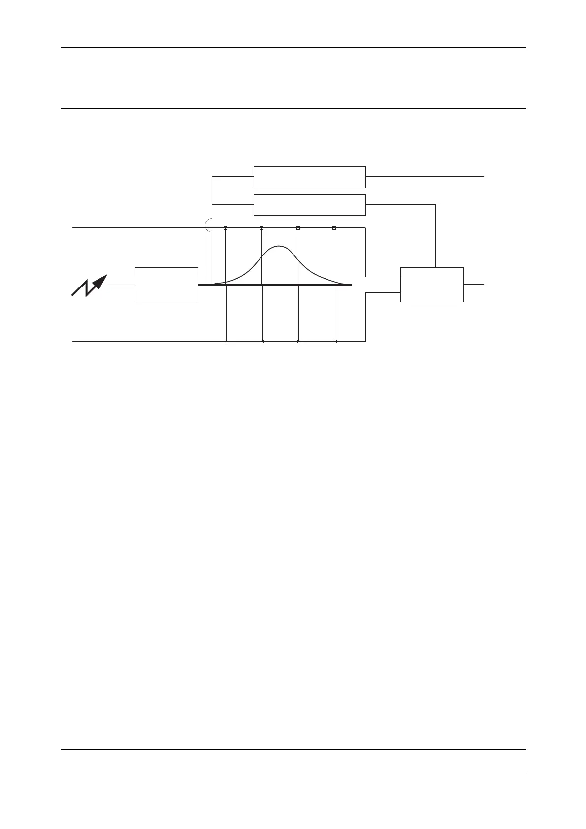
Fig. 3-64 PRB board block diagram
The receiver fibre and the reference fibre are both connected to the receiver diode that converts the
optical signal to an electrical signal. The signal is then amplified and measured.
The measuring is done in two channels and on four positions. By having two channels makes it
possible to collect twice as much data as having one channel, ex. one channel can be used to measure
the reference pulse and one for measuring the received external pulse.
The measured data are A/D-converted and sent to the processor on TPB board. The processor will
calculate the distance and send the information to the IPC board.
PRB also contains signal level detection for controlling the grey wedge and start/stop pulse
generation for coarse distance measurement by TPB.
Greywedge motor assembly
The unit consists of:
• Stepper motor
• Greywedge disc
• GMB (Greywedge Motor Board) board
The GMB board is soldered to the motor and connected to TPB board. The motor is driven by the
GMB board but controlled from the TPB board.
The Greywedge motor assembly is mounted in the Tx/Rx fibres holder and connected to the TPB
board and replaced as one spare part.
RX diode
AD
converter
Coarse measurement
Greywedge control
TPB
TPB
Measurement pulse 1
Measurement pulse 2