Chapter 3
Theory of Operation
Trimble S, VX, SPS & RTS Service Manual3 - 38 P/N 57150002, Revision 5.0
F
MSB board compatibility
The horizontal and vertical MSB board MUST be of the of a compatible revision. Reason is that the
horizontal and vertical LED light sources on the MSB boards must be the same as they are driven
with the same parameters. See the table below for compatibility:
MSB board
How it works
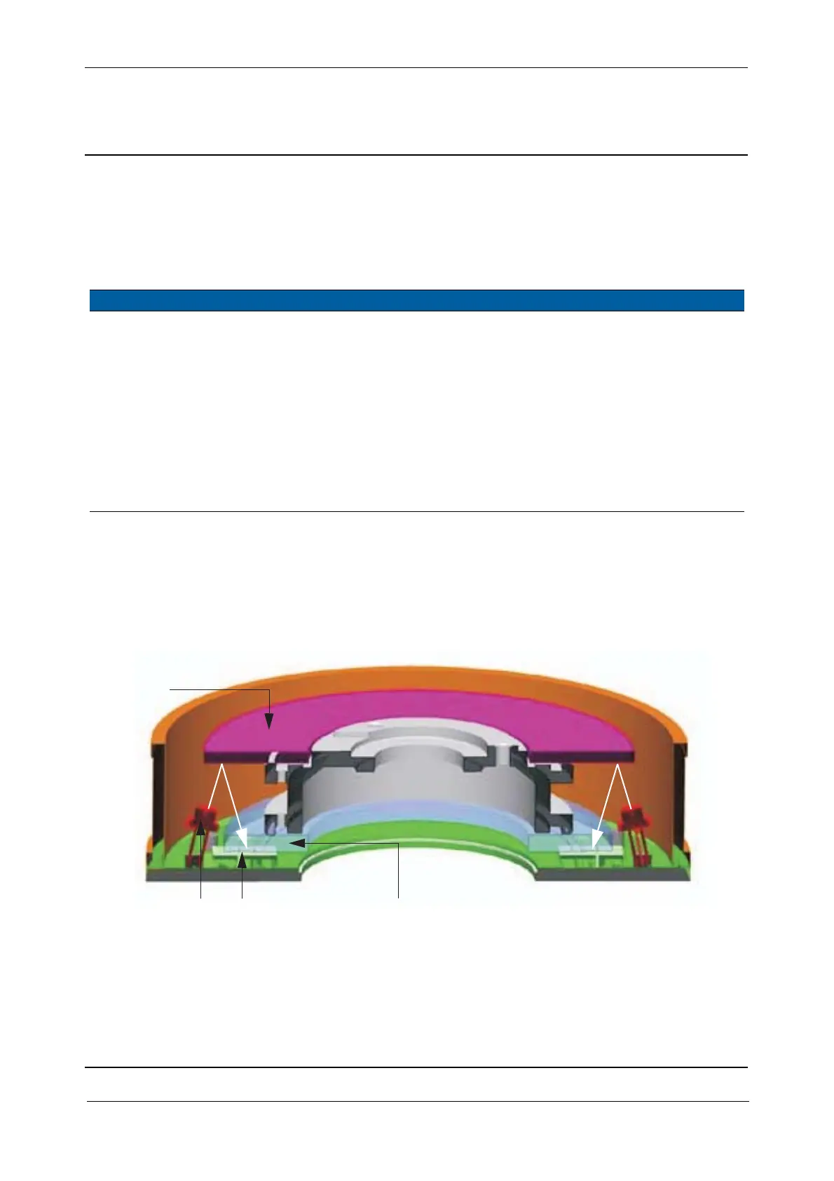
The LED light is reflected by a mirror through an encoder glass disc. A pattern from the encoder glass
disc is projected on the detector. The detector, a CMOS image area reads the pattern from the coarse
and fine code on the disc.
Fig. 3-37 Angle system incl. angle disc
The coarse code placed on the inner circle on the glass disc works like a bar code, the CMOS sensor
will identify the coarse position of the circle. The fine code placed on the outer circle of the glass disc
is an incremental code. By reading the coarse and the fine code an angle can be generated.
Hor. MSB board version Vert. MSB board version Compatibility
1 1 Ver. 1 is ONLY compatible with ver. 1
3 3 Version 3, 4 & 5 are compatible with each other,
i.e. it is possible to have a horizontal MSB ver. 3
and a vertical MSB ver. 5.
44
55
6 6 Ver. 6 - RoHS is not compatible with earlier
versions.
7 7 Type in ver. 6
LED
Mirror
Encoder glass disc
CMOS detector