Chapter 3
Theory of Operation
Trimble S, VX, SPS & RTS Service Manual3 - 100 P/N 57150002, Revision 5.0
F
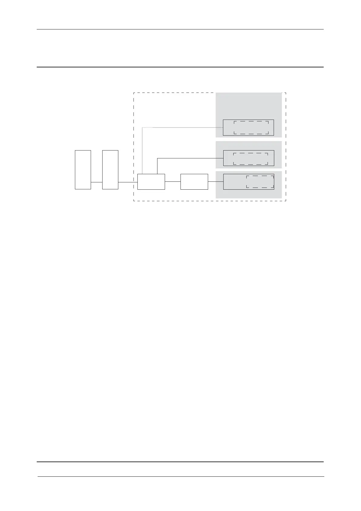
Fig. 3-91 Tracker unit block diagram
Tracker-Transmitter
The functions of the driver boards with transmitter diodes are:
• Controlling the laser transmitter for the standard and TLR tracker
• Class 1 laser safety including a single fault protective circuitry
• Class 3 laser safety including a single fault protective circuitry
Tracker-Receiver
The OTR board incl. quadrant detector:
• Receives the signal via the quadrant detector
• Converts the signal from the quadrant detector to a proportional current and amplify the signal
if necessary
The OTA board:
• Converts the signal to a vertical and horizontal deviation signal
• Amplifying the signal
The OTC2 board:
• Rectifies and low pass filtrates the signals, A/D converted and sent to the processor.
• Controls coarse/fine segments on the receiver quadrant detector
• Controls amplification on the OTR and OTA board
OTR
Quadrant
detector
OTA
OTC2
Transmitter
Receiver
Tracker unit
S
F
C
I
P
C
Tracker Long Range
or
High Power Laser
Driver PCB
Driver PCB