Chapter 8
Replacement Parts & Tooling
Trimble S, VX, SPS & RTS Service Manual8 - 4 P/N 57150002, Revision 5.0
F
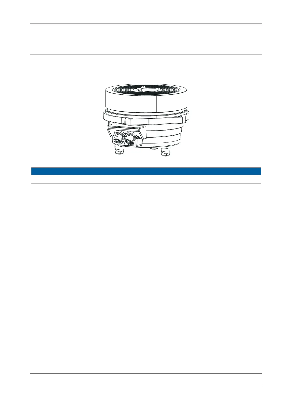
Horizontal Turning Unit - High Angle Accuracy
Horizontal turning unit - 1”
Item Description Part Number Qty
1 Horizontal turning unit High Angle Accuracy - RoHS 59010019 1