Chapter 3
Theory of Operation
Trimble S, VX, SPS & RTS Service Manual3 - 50 P/N 57150002, Revision 5.0
F
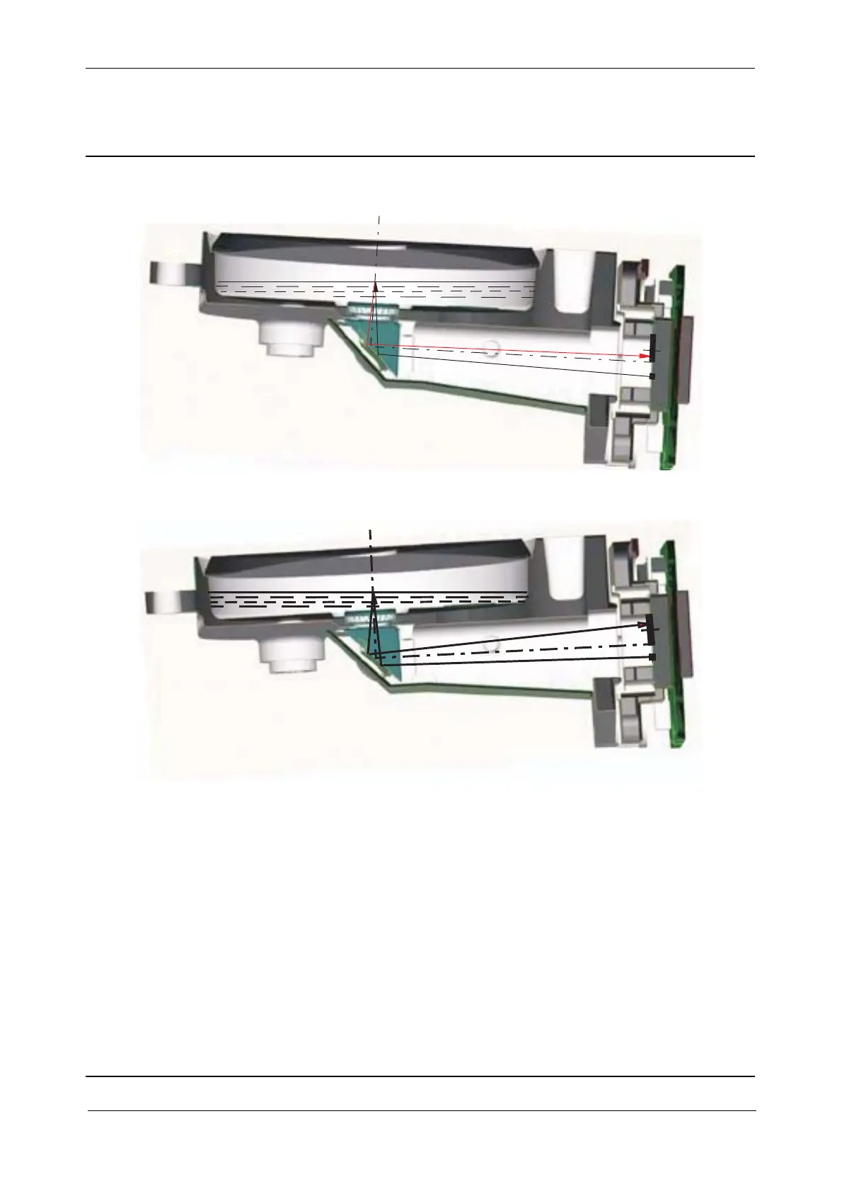
Fig. 3-50 Situation tilt = + 0.5 gon
Fig. 3-51 Situation tilt = - 0,5 gon
The two pictures above are displayed in an overpowered way to give a better impression of the tilted
situation
The principle of the dual axis tilt sensor is to use a light beam that is reflected towards a free liquid
surface via an optical lens. A CMOS image sensor detects the inclination of the light beam in the
measuring direction and perpendicular to this direction.
The tilt sensor includes a PCB board for calculating levelling data. The data is sent to the processor
board.
The tilt sensor is pre-calibrated and the correction data are stored in the sensor.
Tilt sensor offset (calibration)
A procedure to calibrate the tilt sensor to establishing a horizontal reference plane relative to the
balanced vertical axis of the instrument during a 360 rotation of the instrument can be made by the