Chapter 5
Maintenance and Repair
Trimble S, VX, SPS & RTS Service Manual5 - 6 P/N 57150002, Revision 5.0
F
Side covers
• Disassembly
• Assembly
Tools and equipment
Disassembly
Performance
Assembly
The following instruction is valid for servo and radio/battery side cover.
Performance
Description Part number
Torque wrench 120 Ncm T71600280
Torx T10 bit Local tool
Item Performance Action Result Notes
1 Remove servo &
battery/radio side
cover.
Loosen the three screws
with washers and remove
the cover.
Item Performance Action Result Notes
1 Identifying
conductive gasket
joint.
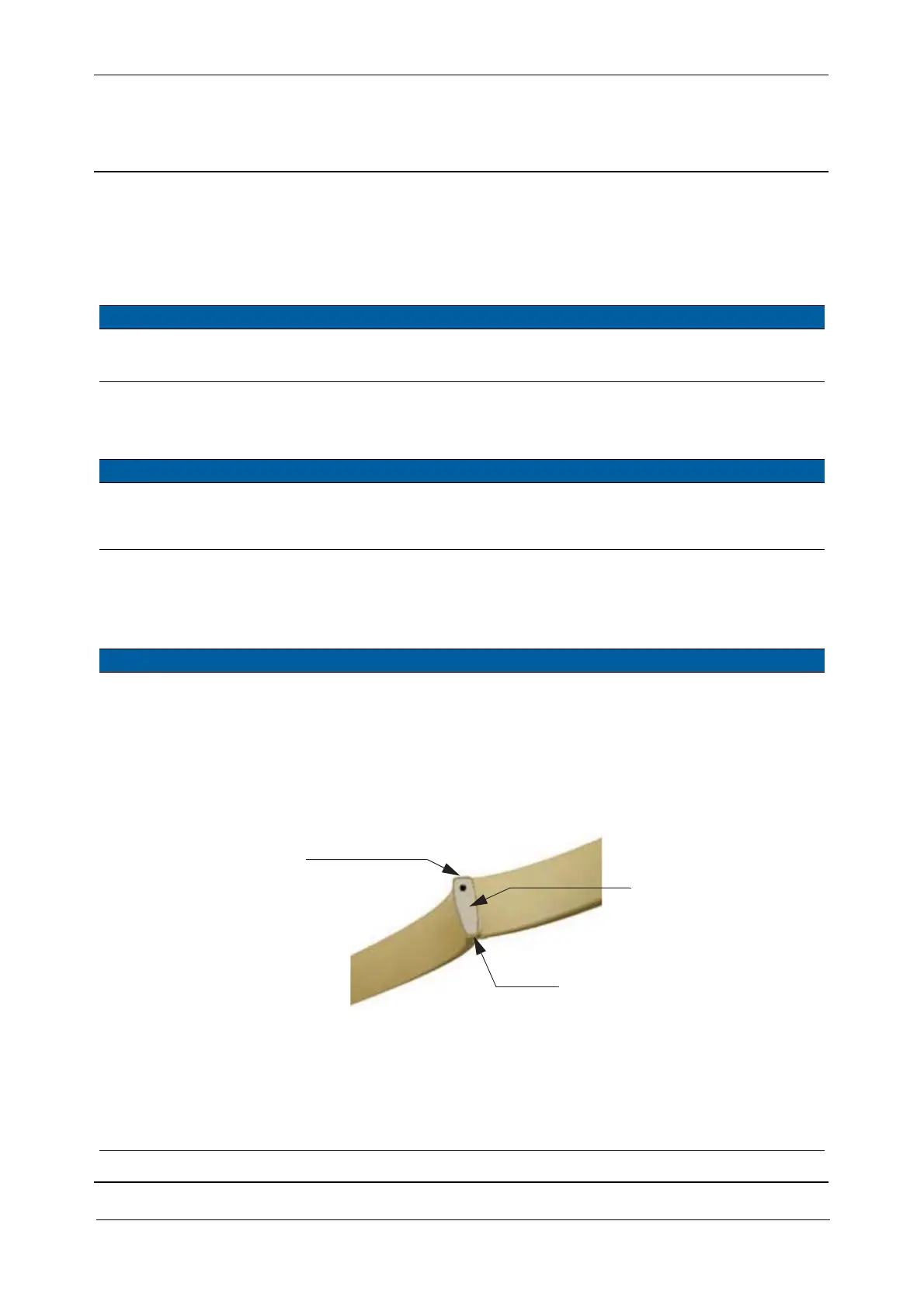
The gasket is shielded on
three sides: top, bottom
and inside. The shielded
sides are light brown and
the un-shielded side is
grey.
The gasket is made
narrow at the bottom
to fit into the side
covers.
Fig. 5-7 Conductive sealing joint
2 Mount conductive
gasket in side cover.
Mount the gasket in the
side covers, the joint must
be placed at position A and
the un-shielded side of the
gasket must face towards
the outside of the covers.
Top of gasket
Narrow bottom of gasket
Joint