Chapter 3
Theory of Operation
P/N 57150002, Revision 5.0 3 - 99 Trimble S, VX, SPS & RTS Service Manual
F
Function description
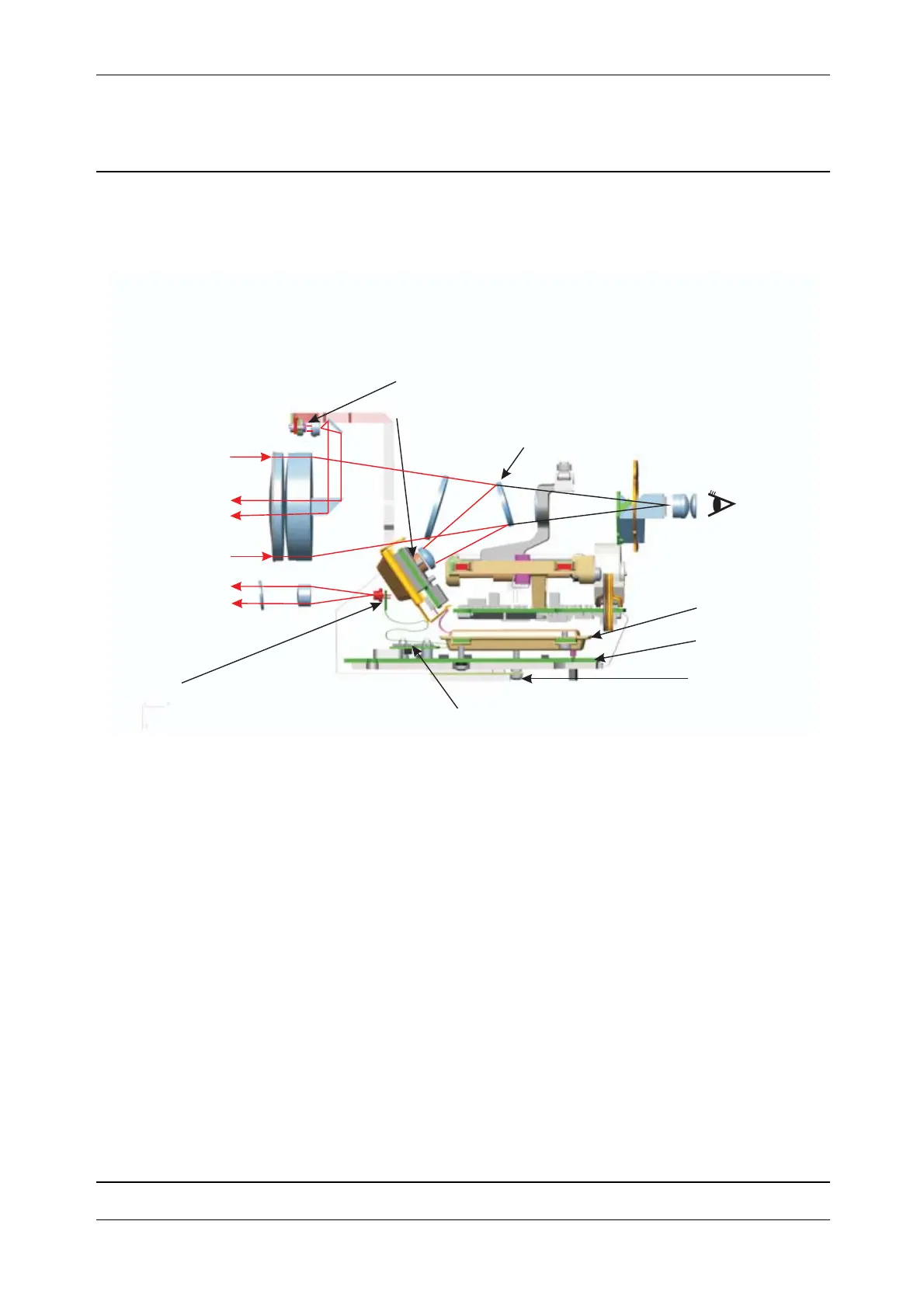
Fig. 3-90 Tracker Long Range working principle
Block diagram
The tracker consists of two
transmitter and one receiver unit.
The
transmitter units include:
• TFB board with transmitter diode (Standard tracker)
• Driver board with transmitter diode (TLR)
The
receiver unit includes:
• OTR board with receiver detector
• OTA board
• OTC2 board, same function as the OTC board but includes TLR and HPL functionality
OTA board
OTC2 board
TFB board
OTR board with receiver detector
Standard tracker transmitter diode
TLR transmitter diode
TLR diode driver board
Selective mirror 785nm