Clock Generation and Control
Élan™SC520 Microcontroller User’s Manual 5-9
5.5.2 Using the CLKTIMER[CLKTEST] Pin
The CLKTIMER[CLKTEST] pin can be programmed as an input (CLKTIMER) or as an
output (CLKTEST) in the Clock Select (CLKSEL) register (MMCR offset C26h).
■ When programmed as an input (default), this pin can be used to provide the clock for
the programmable interval timer (PIT) core. See “Using the PIT Clock Source in PC/AT-
Compatible Systems” on page 16-6 for more information. While the pin is being enabled
as an input, it is synchronized to the CPU clock to prevent spurious pulses from occurring
in the PIT core.
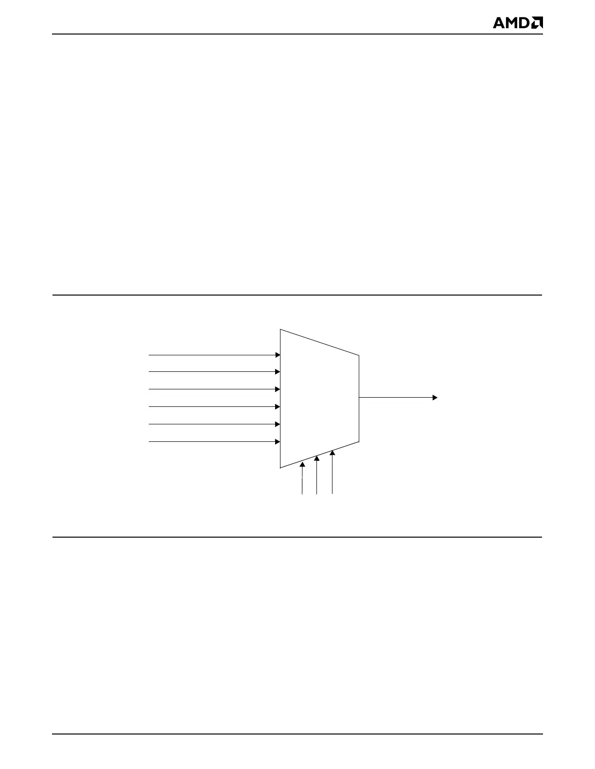
■ When programmed as an output, this pin, as CLKTEST, can drive one of several of the
internal clocks outside the microcontroller for testing or drive an external device.
Figure 5-5 shows the available clocks that can be directed to the CLKTEST pin by
programming the Clock Select (CLKSEL) register (MMCR offset C26h).
Note: Caution should be exercised when programming the CLKTIMER[CLKTEST] pin as
an output, since there is no logic to avoid spurious pulses while enabling or changing clock
frequencies. The target device should be held in reset, the CLK_TST_SEL bit field
programmed to the correct frequency, the CLK_PIN_DIR bit set to 1 (output), and the
CLK_PIN_ENB bit set to 1 (enabled). Then, the target device can be released from reset.
Figure 5-5 Clock Routing for the CLKTEST Pin
5.6 INITIALIZATION
The Am5
x
86 CPU core is reset during a system reset, and the CPU core clock frequency
defaults to 100 MHz. A soft reset does not affect the CPU core clock frequency.
The CLKTIMER[CLKTEST] pin is disabled on reset and must be enabled via the Clock
Select (CLKSEL) register (MMCR offset C26h) before it will function.
See Figure 5-1 on page 5-2 and Table 5-1 on page 5-2 for start-up information. See also
Figure 6-3 on page 6-9 and the reset timing diagrams in the
Élan™SC520 Microcontroller
Data Sheet
, order #22003.
PLL1 (1.47456 MHz)
PLL2 (36.864 MHz)
PIT (1.1882 MHz)
RTC (32.768 kHz)
CLKTEST
CLK_TST_SEL bits from the Clock Select Register
6:1 Mux
UART (18.432 MHz)
UART (1.8432 MHz)