Boundary Scan Test Interface
Élan™SC520 Microcontroller User’s Manual 25-15
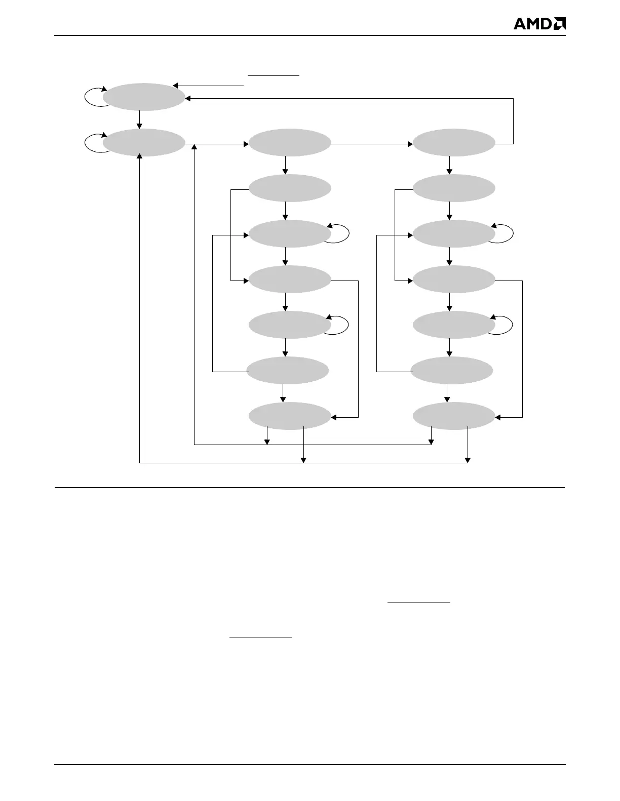
Figure 25-4 Test Access Port Controller State Diagram
25.4.3.1 TAP Controller States
25.4.3.1.1 Test-Logic-Reset State
In this state, the test logic is disabled so that normal operation of the device can continue
unhindered. This is achieved by initializing the Instruction register such that the IDCODE
instruction is loaded. No matter what the original state of the controller, the controller enters
Test-Logic-Reset state when the JTAG_TMS input is held High (1) for at least five rising
edges of JTAG_TCK. The controller remains in this state while JTAG_TMS is High. The
TAP controller is also forced to enter this state when JTAG_TRST
is asserted.
The JTAG TAP controller is not reset as a function of PWRGOOD when the system is
powered up. Rather, JTAG_TRST
has an internal pulldown resistor which causes the TAP
controller to reset.
25.4.3.1.2 Run-Test-Idle State
This is a controller state between scan operations. When in this state, the controller remains
in this state as long as JTAG_TMS is held Low. For instructions not causing functions to
execute during this state, no activity occurs in the test logic. The Instruction register and
Test-Logic-Reset
Run-Test/Idle
0
Select-DR-Scan
0
Capture-DR
0
1
Exit1-DR
0
Pause-DR
1
1
Update-DR
0
0
Shift-DR
Exit2-DR
0
1
1
0
Select-IR-Scan
0
Capture-IR
0
1
Exit1-IR
0
Pause-IR
1
1
Update-IR
0
0
Shift-IR
Exit2-IR
0
1
1
0
1
0
11
111
JTAG_TRST