PCI Bus Host Bridge
Élan™SC520 Microcontroller User’s Manual 9-23
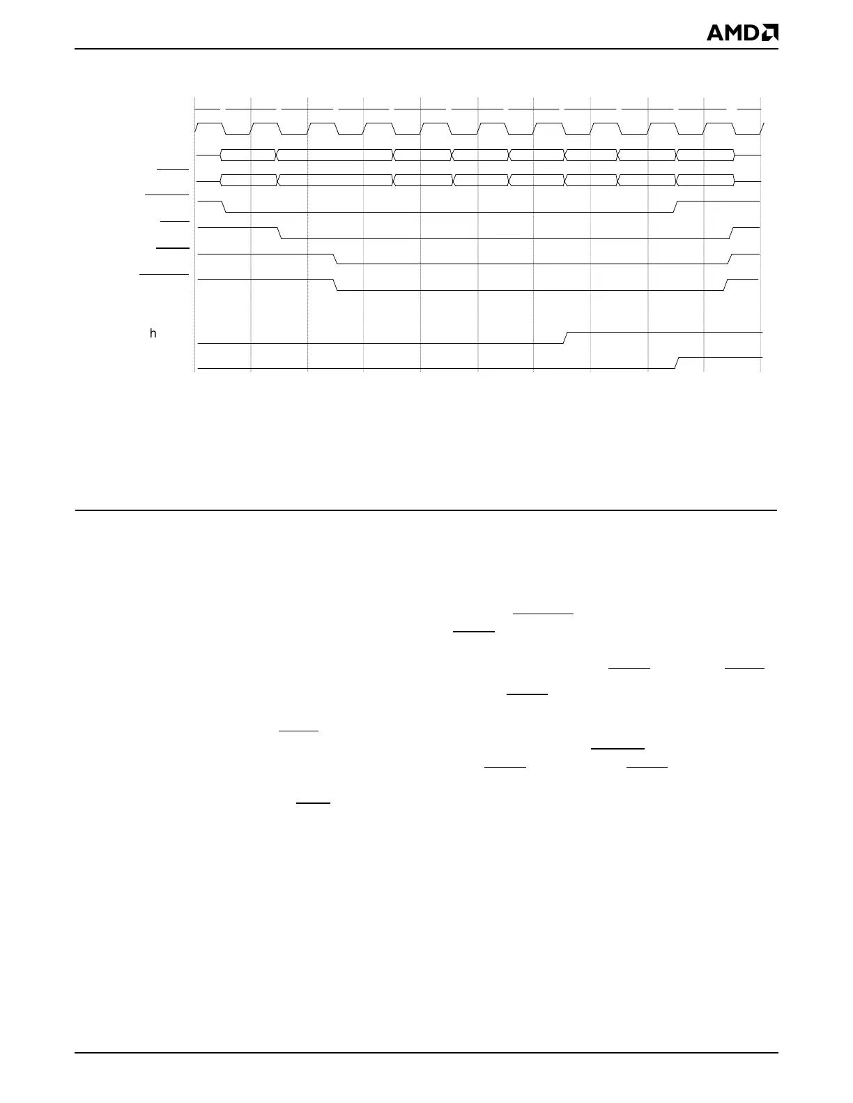
Figure 9-14 External PCI Bus Master Posted Write to SDRAM
The following sequence annotates the external PCI bus master posted write to SDRAM
shown in Figure 9-14.
■ Clock #1: An external PCI master initiates a write transaction to the ÉlanSC520
microcontroller’s SDRAM.
■ Clock #3: The PCI host bridge always asserts DEVSEL with medium timing. In this
example, the write FIFO is not full, so TRDY
is also asserted to accept the write data.
If either the write FIFO or the address FIFO had been full, then the PCI host bridge would
immediately issue a retry to the external master by asserting STOP
instead of TRDY.
■ Clocks #4–#10: The write FIFO is not full, so TRDY remains asserted to accept the
write data. The PCI host bridge does not insert wait states into the PCI transaction by
deasserting TRDY
. If the FIFO becomes full during the transaction but the external PCI
master indicates it is willing to burst more data (by keeping FRAME
asserted), the host
bridge issues a disconnect by deasserting TRDY
and asserting STOP (see
Section 9.5.4.9.3). The external master can insert wait states into the PCI transaction
by deasserting IRDY
. The host bridge is posting the write data (it will be written to SDRAM
sometime later).
■ Clock #7: The PCI host bridge has synchronized the first PCI data phase (Clock #4)
and requests access to the SDRAM controller.
■ Clock #9: The SDRAM controller is granted to the PCI host bridge and the PCI bus data
can be written to SDRAM. The hb_gnt signal may be delayed if the Am5
x
86 CPU or GP-
DMA is accessing SDRAM.
1 2 3 4 5 6 7 8 9 10
address data1 data2 data3
write cmd be1 be2 be3
data4
be4
data5 data6 data7
be5 be6 be7
CLKPCIIN
ADx
CBEx
FRAME
IRDY
TRDY
DEVSEL
hb_req
hb_gnt
Notes:
The diagram includes the following internal signals:
• hb_req: PCI host bridge requesting the Am5
x
86 CPU bus to access the SDRAM controller.
• hb_gnt: PCI host bridge has been granted Am5
x
86 CPU bus and can access the SDRAM controller.
See Chapter 8, “System Arbitration”, for information on Am5
x
86 CPU bus arbitration.
 Loading...