Élan™SC520 Microcontroller User’s Manual 25-1
CHAPTER
25
BOUNDARY SCAN TEST INTERFACE
25.1 OVERVIEW
The ÉlanSC520 microcontroller provides test and debug features compliant with IEEE
Standard Test Access Port (TAP) and Joint Test Action Group (JTAG) (IEEE Std 1149.1-
1990). The test logic is provided to test and ensure that:
■ Components function correctly
■ Interconnections between various components are correct
■ Various components interact correctly on the printed circuit board
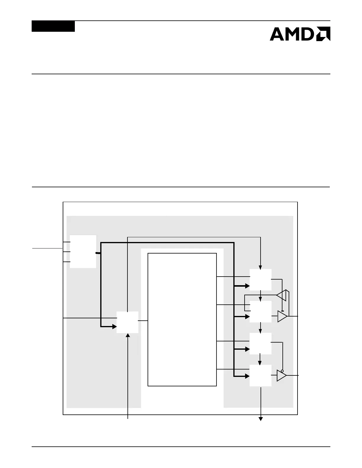
25.2 BLOCK DIAGRAM
Figure 25-1 shows a block diagram of the Boundary Scan register of the ÉlanSC520
microcontroller.
Figure 25-1 Logical Structure of Boundary Scan Register
JTAG_TMS
JTAG_TRST
JTAG_TCK
Controller
TAP
JTAG_TDO
JTAG_TDI
B/S
cell
B/S
cell
B/S
cell
B/S
cell
Boundary Scan Register
On-Chip
System
Logic
B/S
cell
Bidirectional
pins
Output pins
BSR
Control
Élan™SC520 Microcontroller
Input pins