Real-Time Clock
20-2 Élan™SC520 Microcontroller User’s Manual
Figure 20-2 on page 20-3 shows a block diagram of the RTC voltage monitor. The
ÉlanSC520 microcontroller’s RTC voltage monitor is designed to signal the RTC core when
the backup battery is not installed or is low. Additionally, the voltage monitor circuit signals
the RTC core when the rest of the system is being powered down.
As shown in Figure 20-2, the voltage monitor includes a bandgap voltage generator for
precision reference voltage and a high-gain amplifier for adjusting bandgap voltage to “low-
battery” trip voltage. In addition to the backup battery monitor function, the voltage monitor
also provides a power-down signal to the RTC. This signal is used to isolate the RTC core
from the rest of the integrated peripherals. A timing diagram for this sequence is shown in
the
Élan™SC520 Microcontroller Data Sheet
, order #22003.
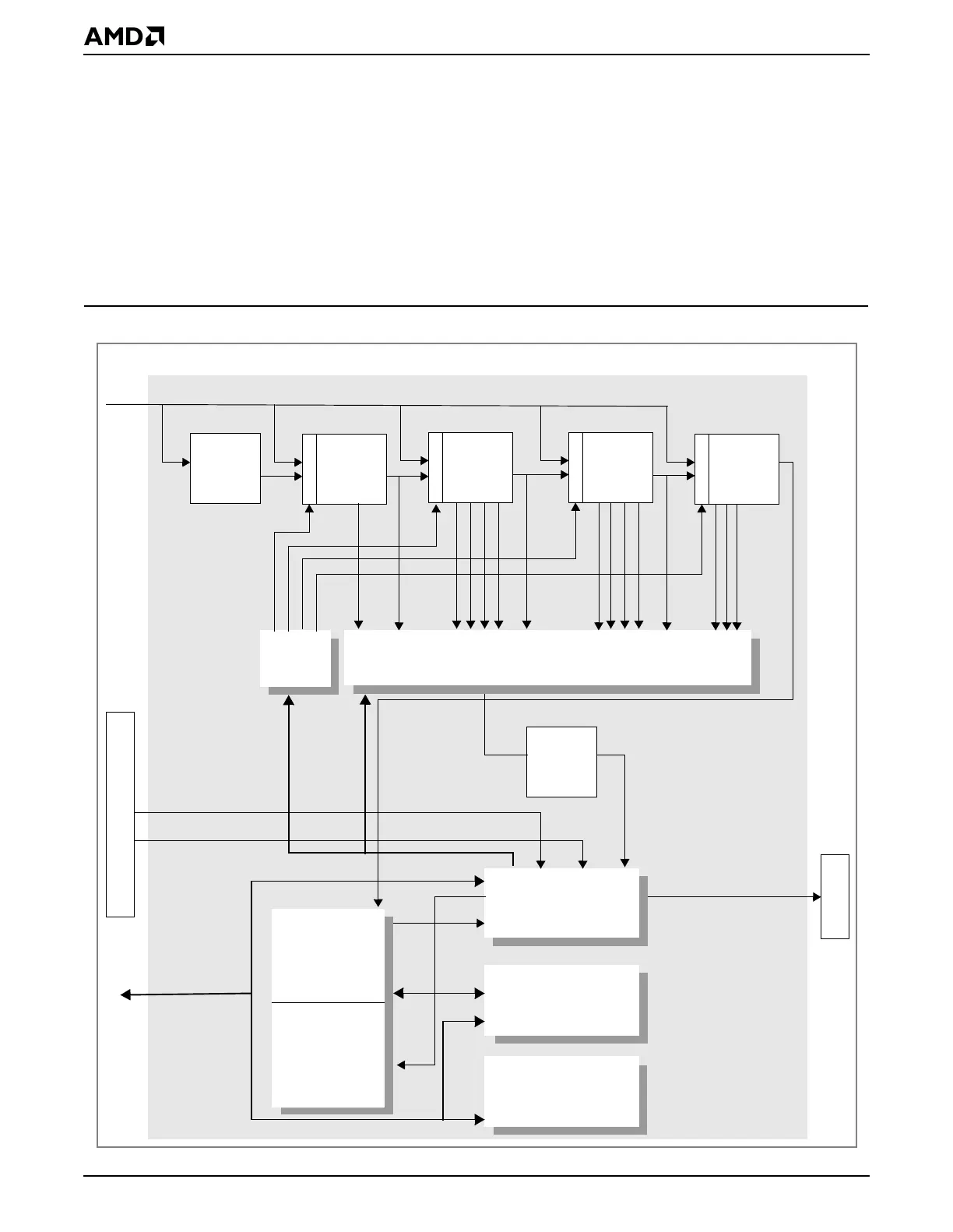
Figure 20-1 Real-Time Clock Block Diagram
Periodic Interrupt Selection
(1-of-15 Selection)
Control and Status
(4 Bytes)
Clock, Alarm
Calendar RAM
(10 Bytes)
Configuration RAM
Clock/
Calendar
Update
BCD/
Binary
Increment
Internal GP bus
interface
rtc_irq
Time Base (32.768 kHz)
1-Hz Clock
OSC_CTL[2–0]
RATE_SEL[3–0]
Real-Time Clock
/32 /32
/2
(114 bytes)
PIC
/32
Divider
/32/4
Control
VMRTC
RTC Voltage Monitor
rst_rtc
pwrdn
Élan™SC520 Microcontroller
Registers A,B,C,D