Watchdog Timer
19-2 Élan™SC520 Microcontroller User’s Manual
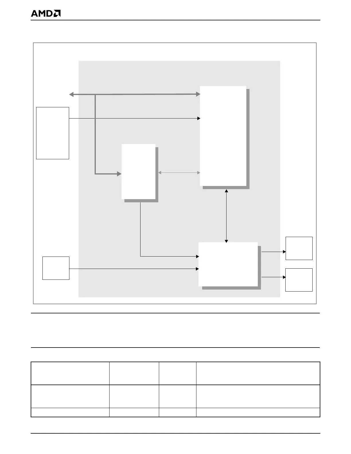
Figure 19-1 Watchdog Timer Block Diagram
19.3 REGISTERS
The watchdog timer is controlled by the memory-mapped registers listed in Table 19-1.
Table 19-1 Watchdog Timer Registers—Memory-Mapped
Register Mnemonic
MMCR
Offset
Address Function
Watchdog Timer Control WDTMRCTL CB0h Watchdog timer enable, WDT reset enable,
interrupt flag, duration of the WDT time-out
interval
Watchdog Timer Count Low WDTMRCNTL CB2h Bits 15–0 of the WDT current count
Internal GP bus
cnt_reset
wdt_rst
wdt_irq
ice_mode
33-MHz Clock
Clock
PIC
Reset
System
Configuration
Registers
Élan™SC520 Microcontroller
Watchdog Timer
Key
Detection
Logic
Configuration
Registers
Counter
Time-Out