General-Purpose Bus Controller
13-14 Élan™SC520 Microcontroller User’s Manual
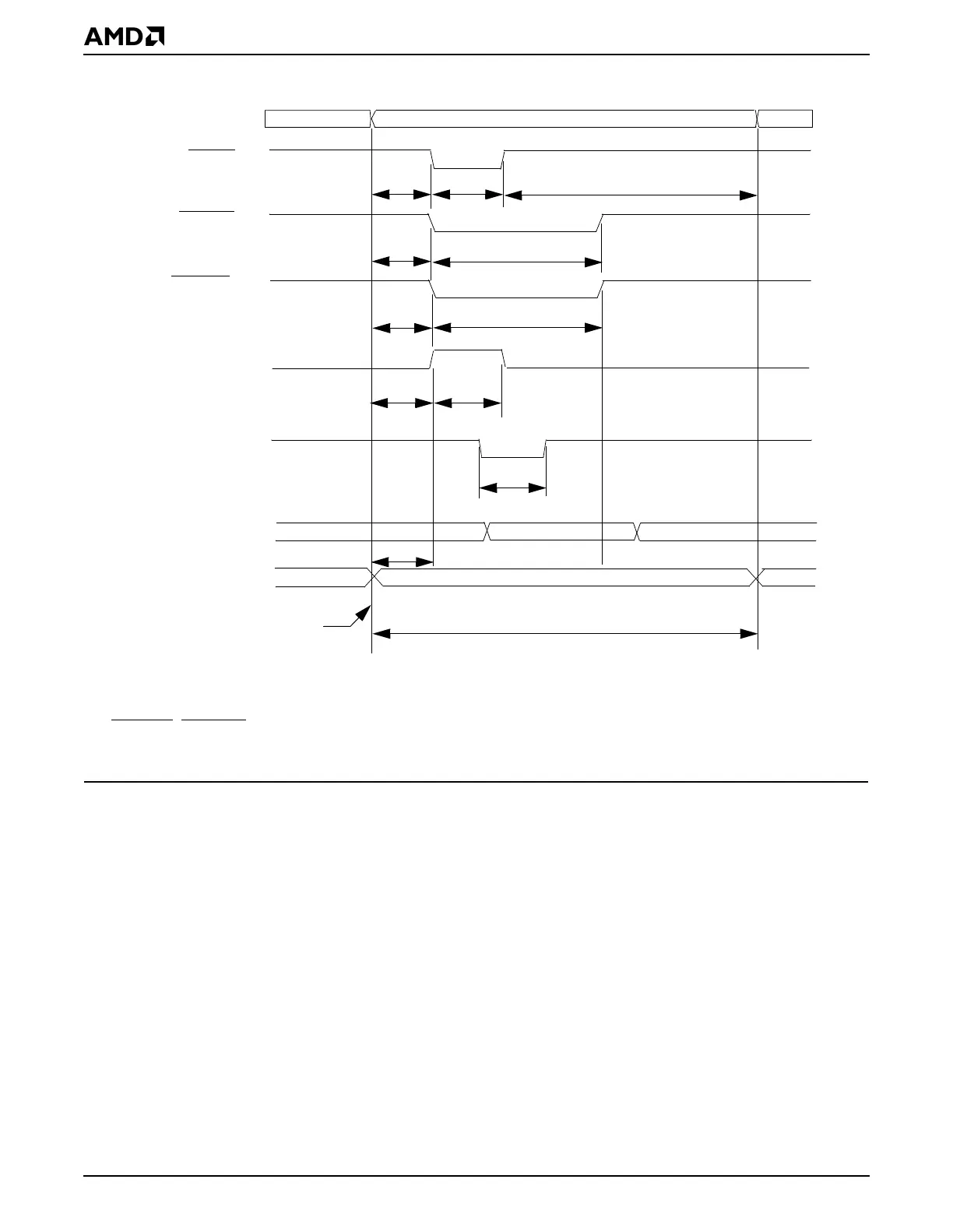
Figure 13-6 Timing Diagram of a Super I/O Interface
13.5.8.3 Interfacing with an AMD Enhanced Serial Communications Controller (8 MHz)
This slow version is depicted to illustrate an example of how the programmable timing can
be used to function with various timing requirements. Figure 13-7 shows an example system
diagram of the ÉlanSC520 microcontroller interfacing with an Am85C30 Enhanced Serial
Communications controller. Table 13-6 and Figure 13-8 show the interfacing timing
example. In this example, the programmable interface timing registers can be programmed
using the equation from “Programmable Bus Interface Timing” on page 13-7.
Address Valid
GPA10
–
GPA0
GPCSx
1
GPIORD
2
GPALE
30 ns
30 ns
30 ns
60 ns+
90 ns+
120 ns
Beginning of a bus cycle
(Not needed)
30 ns
30 ns
GPIOWR
**
30 ns
60 ns+
GPRDY
Trdy
Read Data
Write Data
GPD7
–
GPD0
30 ns
GPD7
–
GPD0
Notes:
1. Although the chip selects are not used, the recovery time needs to be programmed.
2. GPIORD
, GPIOWR, and the chip select recovery time are delayed when the GPRDY signal is deasserted.
3. This example assumes that a 33.333-MHz crystal is being used in the system.