Programmable Interrupt Controller
15-2 Élan™SC520 Microcontroller User’s Manual
15.2 BLOCK DIAGRAM
Figure 15-1 is a block diagram of the ÉlanSC520 microcontroller’s programmable interrupt
controller showing interrupt sources and routing.
The programmable interrupt controller consists of a system of three individual interrupt
controllers (Master, Slave 1 and Slave 2), each of which has eight interrupt channels. Two
of the interrupt channels on the Master controller are used to cascade the slave controllers.
This allows a total of 22 interrupt priority levels in the ÉlanSC520 microcontroller. The priority
levels are numbered from P1–P22 to indicate which priority levels are assigned to slave or
master controllers, with P1 being the highest and P22 the lowest priority.
15.3 SYSTEM DESIGN
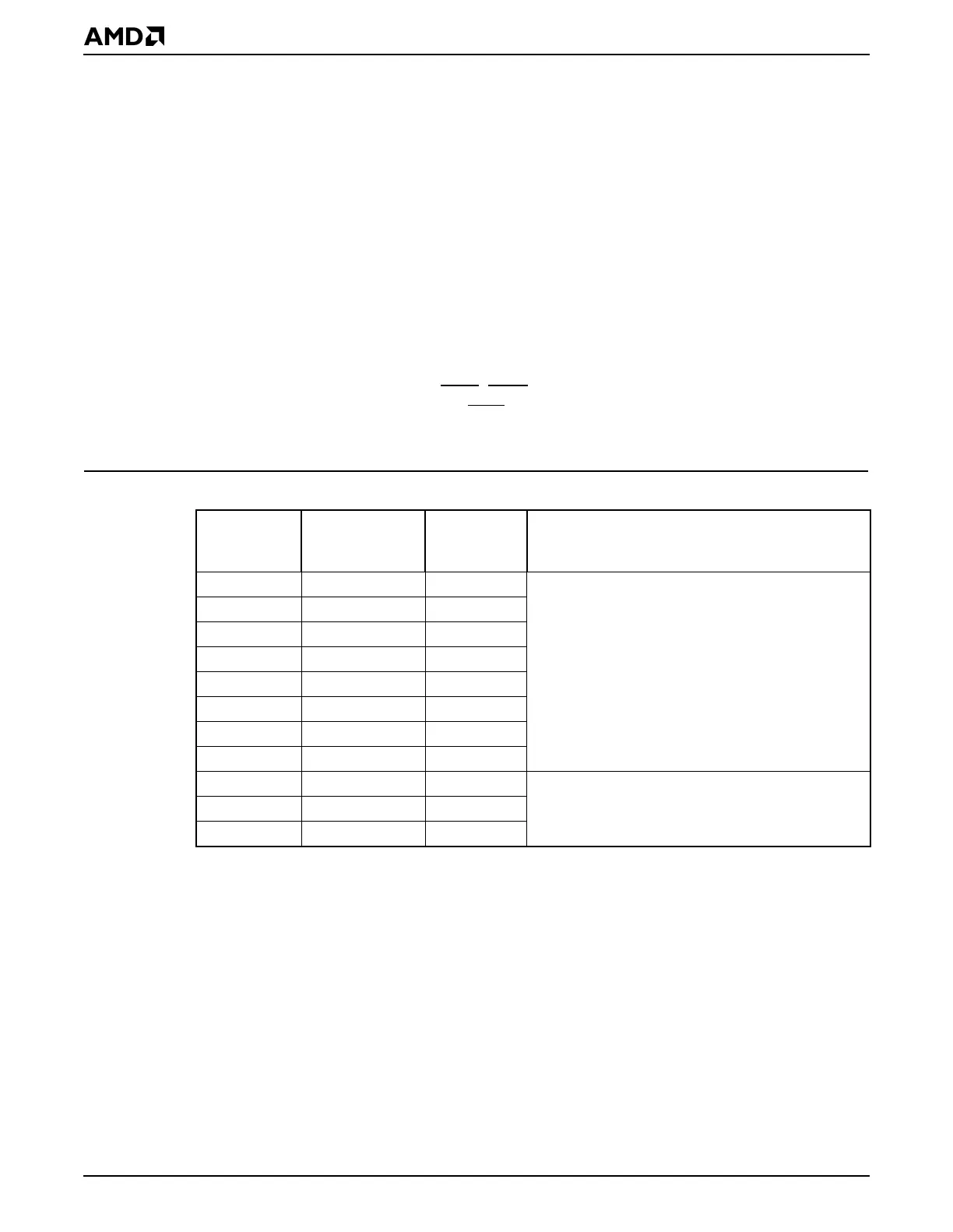
Table 15-1 shows PIC signals shared with other interfaces. When enabled, the multiplexed
signals shown in Table 15-1 either disable or alter any other function that uses the same pin.
The GPIRQ10–GPIRQ0 and INTA–INTD signals are asserted when a peripheral requires
interrupt service. The dedicated INTA
–INTD pins are the same type of interrupt as the
GPPIRQx signals. They are named INTx
to match the common PCI interrupt naming
convention.
Table 15-1 Programmable Interrupt Controller Signals Shared with Other Interfaces
PIO
(Default)
Function
Interface
Function Control Bit Register
PIO23 GPIRQ0 PIO23_FNC
PIO31–PIO16 Pin Function Select
(PIOPFS31_16) register
(MMCR offset C22h)
PIO22 GPIRQ1 PIO22_FNC
PIO21 GPIRQ2 PIO21_FNC
PIO20 GPIRQ3 PIO20_FNC
PIO19 GPIRQ4 PIO19_FNC
PIO18 GPIRQ5 PIO18_FNC
PIO17 GPIRQ6 PIO17_FNC
PIO16 GPIRQ7 PIO16_FNC
PIO15 GPIRQ8 PIO15_FNC
PIO15–PIO0 Pin Function Select
(PIOPFS15_0) register (MMCR offset C20h)
PIO14 GPIRQ9 PIO14_FNC
PIO13 GPIRQ10 PIO13_FNC