Pin Information
2-4 Élan™SC520 Microcontroller User’s Manual
2.3 SIGNAL DESCRIPTIONS
Table 2-1 describes the terms used in the signal description table. In general, the brackets,
[ ], indicate alternate, multiplexed functions, and braces, { }, indicate reset configuration
pins (pinstraps). The line over a pin name indicates an active Low signal. The word pin
refers to the physical wire; the word signal refers to the electrical signal that flows through it.
Table 2-2, “Signal Descriptions” on page 5 contains a description of the ÉlanSC520
microcontroller signals. The descriptions in Table 2-2 are organized by functional group.
Table 2-2 describes the signals that are available for each interface and which signals are
shared with others. Signal sharing is also shown in Figure 2-2.
Detailed information on pin state, including maximum load values, power-on reset default
function, reset state, power-on reset default operation, hold state, and voltage, is available
in the
Élan™SC520 Microcontroller Data Sheet
, order #22003. Connection and package
diagrams, as well as pin number assignments, are also included in that document.
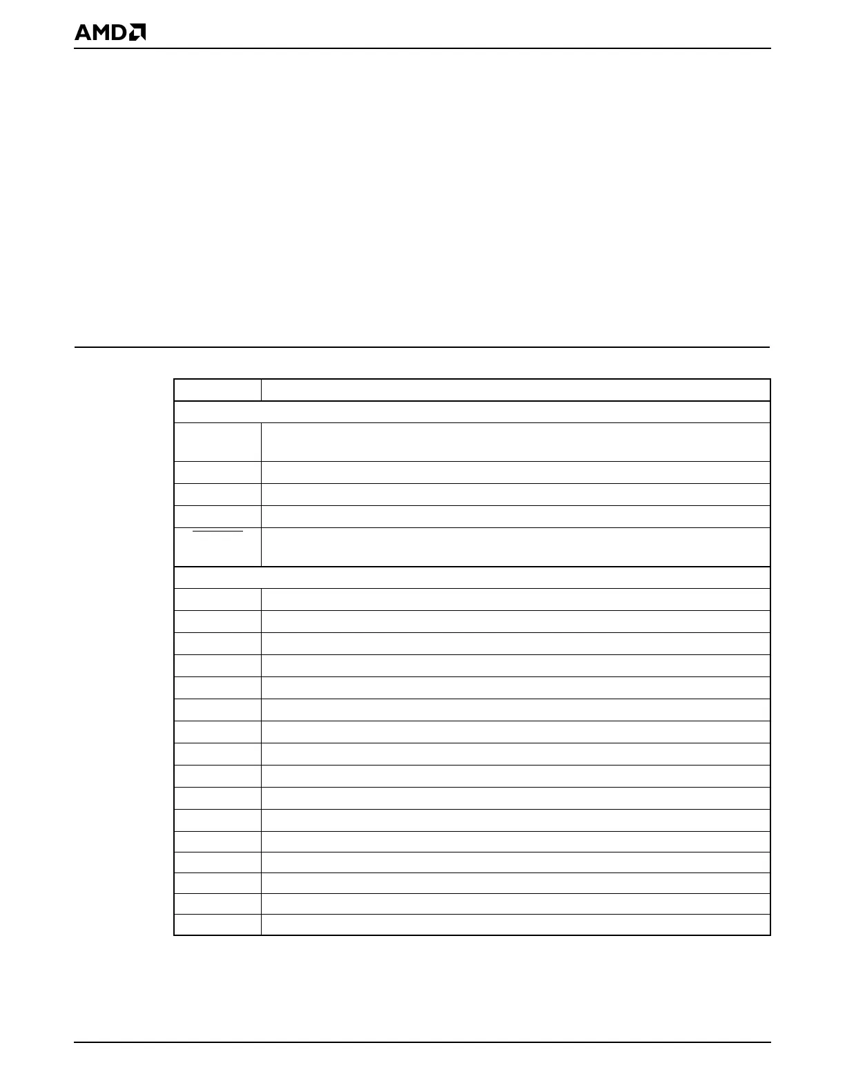
Table 2-1 Signal Descriptions Table Definitions
Term Definition
General Terms
[ ] Indicates the pin alternate function; a pin defaults to the signal named without the
brackets.
{ } Indicates the reset configuration pin (pinstrap).
pin Refers to the physical wire.
signal Refers to the electrical signal that flows across a pin.
SIGNAL
A line over a signal name indicates that the signal is active Low; a signal name
without a line is active High.
Signal Types
Analog Analog voltage
B Bidirectional
HHigh
I Input
LS Programmable to hold last state of pin
O Totem pole output
O/TS Totem pole output/three-state output
OD Open-drain output
OD-O Open-drain output or totem pole output
Osc Oscillator
PD Internal pulldown resistor (~100–150 kΩ)
Power Power pins
PU Internal pullup resistor (~100–150 kΩ)
STI Schmitt trigger input
STI-OD Schmitt trigger input or open-drain output
TS Three-state output