System Arbitration
8-20 Élan™SC520 Microcontroller User’s Manual
8.4.7 Latency
Because the PCI bus is shared by many masters, each master incurs a latency accessing
the bus due to other masters. This latency is determined by each master in the system and
the arbitration algorithm. The latency contributed by each master is controlled through its
associated master latency timer, which limits the amount of time a master is allowed for
each transaction. When this timer expires, the current master must end its transaction and
allow another master access to the bus.
The ÉlanSC520 microcontroller PCI bus arbiter has two rotating priority queues and an
Am5
x
86 CPU relative priority. The Am5
x
86 CPU does not burst on PCI, and therefore does
not have a master latency timer. The longest transaction for the Am5
x
86 CPU is 16 PCI
clocks.
The latency contributed by the ÉlanSC520 microcontroller PCI bus arbiter can be controlled
in the Arbiter Priority Control (ARBPRICTL) register (MMCR offset 74h) through the use of
the high-priority queue and the relative Am5
x
86 CPU priority configuration.
8.4.7.1 Simple Rotating Priority Latency
In a simple one-level rotating priority queue, the maximum latency for each master would
be the sum of all the other master latency timers in the system.
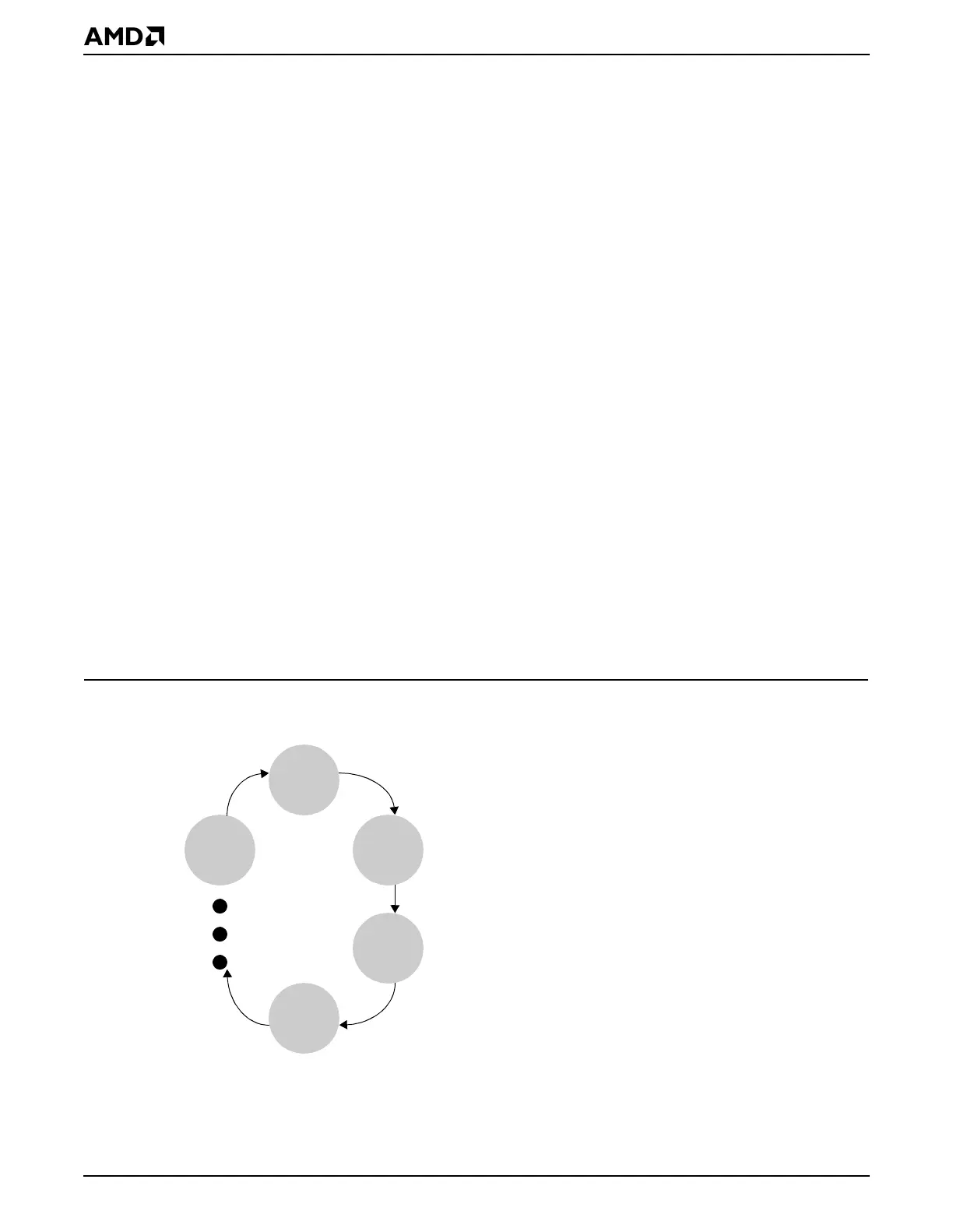
In Figure 8-12, the maximum latency for master M0 would be the sum of the longest possible
transactions for masters M1, M2, M3, ..., Mn. The longest transaction for each master is
limited by its associated master latency timer, so the maximum latency for M0 would be:
master latency timer for M1 + master latency timer for M2 + master latency timer for M3 +
... + master latency timer for Mn
This latency would be seen by M0 when it had just completed a transaction, all other masters
were requesting access to the bus, and each master required the bus for the entire duration
of its associated master latency timer.
Figure 8-12 Simple Rotating Priority Queue
M0
M1
M2
M3
Mn